Ph Diagram For Refrigeration Cycle
It is recommended that the engineer get a copy of the p h diagram for r 134a and the other common refrigerants. Figure 1 9 p h diagram for the refrigeration system figure 1 10 refrigerant flow diagram for the refrigeration system.
 Lecture Note Refrigeration Cycle
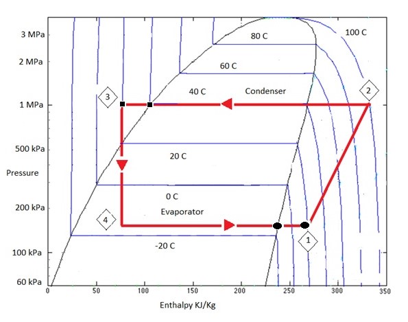
Figure 4 is a pressure enthalpy diagram of a typical refrigeration cycle in a system with one pound of hfc 134a.
Ph diagram for refrigeration cycle. The ordinary household refrigerator is a good example of the application of this cycle. It makes our life much easier. Consider now a multistage situation in which two cycles are combined.
Take the system operating pressures and convert them to absolute pressure by adding 15 these pressures will be used to establish the evaporator and condenser lines. The p h diagram of the refrigeration cycle with all the operating conditions are as the following. The basic refrigeration cycle for beginners if you are interested in learning how a refrigeration system works it is helpful to understand from the ph pressure enthalpy chart perspective.
It uses for this example evaporating and condensing temperatures of 0f and 120f. Points on the diagram are labeled to correspond to locations of equipment in the system. As we can see in the ph diagram below.
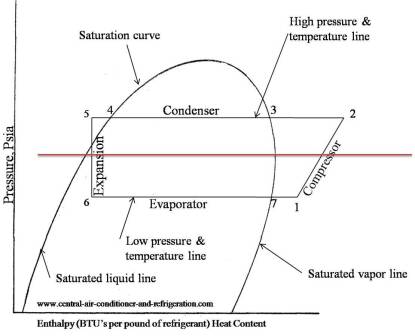
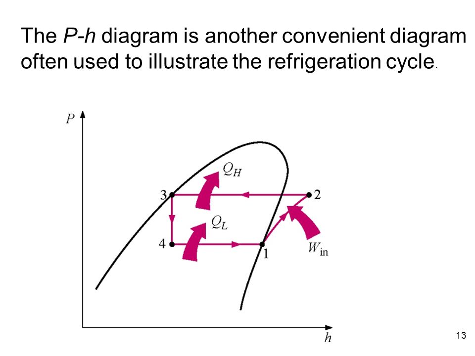
Saturation curve this curve represents what state vapor or liquid and region sub cooled latent heat and superheat the refrigerant is in. How does basic refrigeration cycle work. The p h diagram is another convenient diagram often used to illustrate the refrigeration cycle.
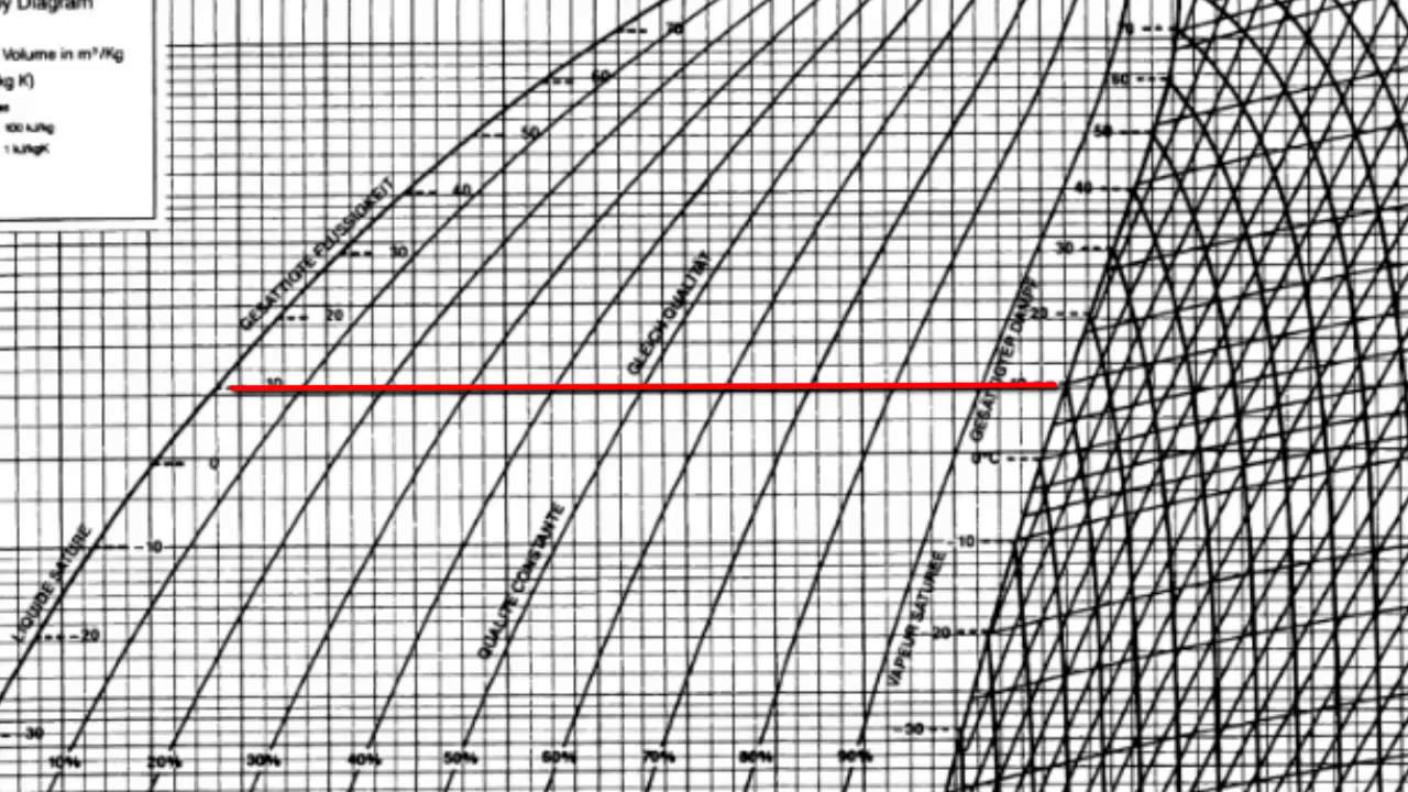
A p h diagram for r22 in si unit is used. These diagrams can be found in the ashrae fundamentals book. The first step in plotting a refrigeration cycle on a ph diagram is to establish the condensing and evaporating lines.
Figure 1 provides a schematic diagram of the components of a typical vapor compression refrigeration system. When you can draw a refrigeration cycle on a p h diagram you can easily obtain the refrigerant characteristics through the diagram. Yoshihiro udagawa toshiba carrier corporation.
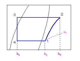
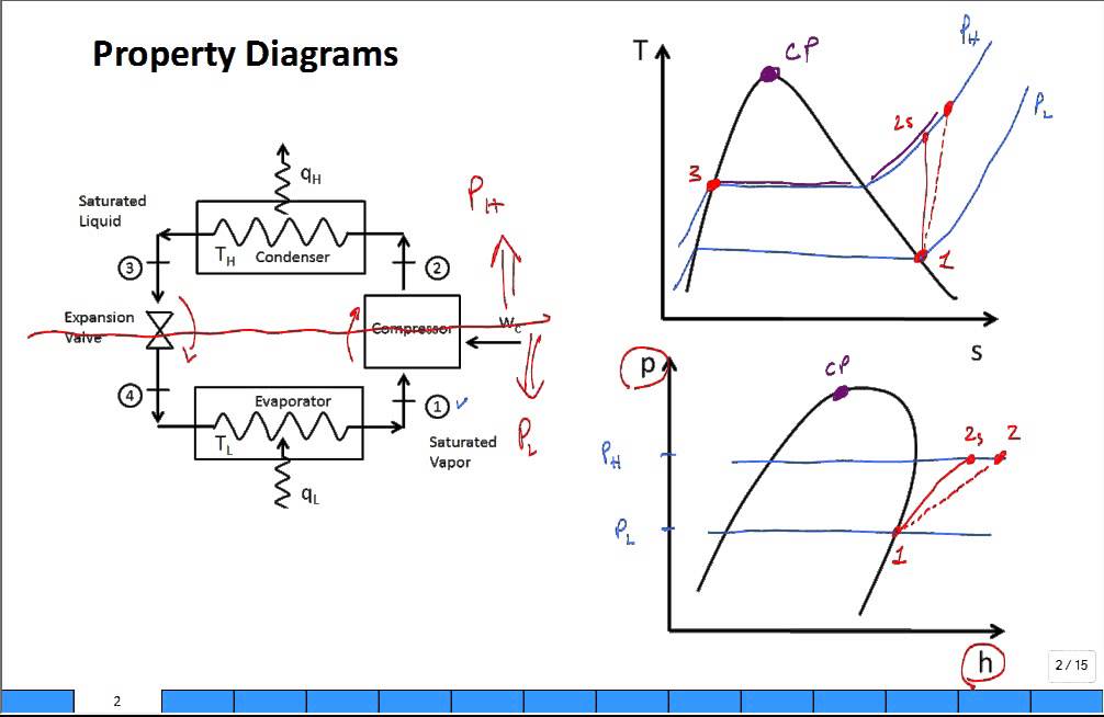
Results of first and second law analysis for steady flow component process first law result compressor s const. One stage subcooler desuperheater refrigeration cycle. Vapor compression refrigeration the thermodynamics of the cycle can be analysed on a diagram 4 5 as shown in figure 2.
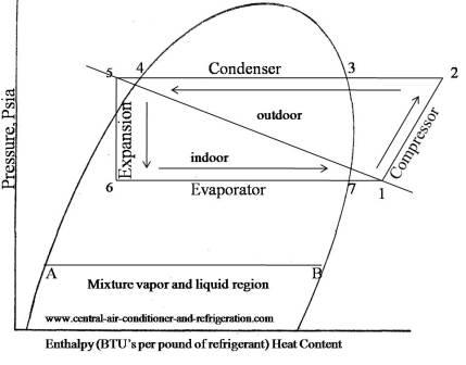
Lets study about how to draw a refrigerant cycle in series using the documents with courtesy of mr. Ts and p h diagram for liquid sub cooling in a refrigeration cycle. A sample r 134a diagram is shown below with a sample refrigeration cycle identifying step 1 evaporator step 2 compressor step 3 condenser and step 4 expansion device.
Wmhh in 21. This is how the refrigeration cycle diagram looks. Understanding the basic refrigeration cycle diagram also helps us to find subcooled superheat and to troubleshoot refrigeration processes much easier.
 Chapter 14a Vc And Ac Refrigeration Cycles And Systems Ppt Download
 Schematic Diagram Of Ejector Expansion Transcritical Refrigeration
 Chapter 9 Carbon Dioxide R744 The New Refrigerant Updated 3 17 2013
 P H Diagram Of Vapor Compression Refrigeration Cycle Generally The
 1 Ref Cycle Explained On P H Diagram Yanbu Industrial College
Jsrae Japanese Society For Refrigerating And Airconditioning Engineers
 Refrigerant Ph Diagram Heat Exchangers Buffalo Brewing Blog
 P H Diagram R22 7 14 Stromoeko De
 Examining High Suction Pressure Hvac Brain

 Refrigeration Cycles Mech Engineering Thermodynamics Ucl Wiki
 P H Diagram Of The Refrigerant R22 N Refrigeration Cycle The

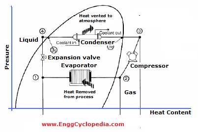 Typical Vapor Compression Refrigeration Vcr Cycle Enggcyclopedia

 Refrigeration Cycles د محمود عبدالوهاب Ppt Download
 Solved This Is A Ph Diagram Of A Refrigerant Sketch An
 P H Chart For Refrigeration Cycle Pdf Homeschoolingforfree Org
 Ph Diagram Of The Thermodynamic Cycle Of An Ideal Refrigeration Unit
 Chapter 9 Carbon Dioxide R744 The New Refrigerant Updated 3 17 2013
 Property Diagrams Ts And Ph For Refrigeration 2 Youtube
 Refrigeration Cycle For Ideal Conditions On A Pressure Enthalpy
0 Response to "Ph Diagram For Refrigeration Cycle"
Post a Comment