Ethane Cracker Process Flow Diagram
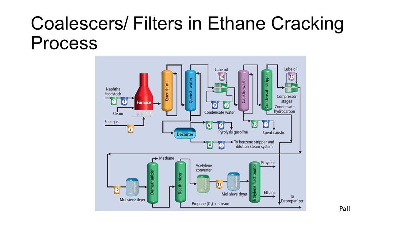
The process shown in figure 1 is a steam cracking process for ethylene production from an ethane propane mixture. In the convection zone hydrocarbon feed stock.
 Advances In Ethane Cracking Ppt Download
Naphtha ethane propane gas oil etc.

Ethane cracker process flow diagram. The ethane crackers fuel consists of a mixture of recycled tail gas hydrogen rich and natural gas methane with a heating value of 523 btuscf. Steam cracker 170 mw heat duty modeled as 2 100mw separate pyrolysis furnaces each furnace 100 mw capacity operates at 80 capacity. Advances in ethane cracking.
Flow diagram for pyrolysis of napththa is given in figure m vii 21. The process can be divided into three main parts. About these slides the slides in this collection are the talking points that guided our discussion at the 2012 pa wib symposium with approximately 40 symposium participants.
Process flow diagrams and descriptions for uop exxonmobil and dalian institute of chemical physics dicp technologies are given. Naphtha and gas cracking for production of olefins. Cracking the ethane cracker.
An ethylene steam cracker can accept a variety of feedstock. In the case of steam cracking of the ethane and propane it is convenient to. The olefins are widely produced using thermal cracking of light hydrocarbons such as ethane propane n butane and their mixtures.
The use of ethanol to make ethylene on a comparatively small scale is well established in developing countries not having ready access to hydrocarbons. The choice of feedstock can depend on the cracker furnace construction the availability of the particular feed its current market price and the desired end products. Image courtesy of cbi in ethane cracking fresh feedstock and recycled ethane are thermally cracked in the presence of steam in a bank of pyrolysis furnaces.
The content and flow of the slides provides an outline of our remarks but not their detail. Ethylene from renewable sources. Can be cracked to produce ethylene.
Normal operation assumes five furnaces continuous operation and one furnace on hot stand by or decoking operations. Simulation and analysis of ethane cracking process. Process flow diagram for ethane cracking.
Linde 713 873 1708. Hot section it consists of convection zone and radiant zone. A mixture of inert steam and hydrocarbon feed stocks are entered into coiled tubular reactors with high temperatures and short residence times.
 Process Flow Diagram Methanol To Olefins Process 13 14 Download
Process Design Overview For Upgrading A Gas To Methanol Facility
 Ethane Cracker Process Flow Diagram
 15 Lovely Ethylene Cracker Process Flow Diagram Www Iaeifl Org
Ethane Cracking Process Related Keywords Suggestions Ethane
 Advances In Ethane Cracking Ppt Download
New Catalytic Olefins Technology
Lecture 13 Petrochemicals Overview

 4 Catalytic Conversion Of Light Alkanes The Changing Landscape Of
 What The Heck Is An Ethane Cracker
 Shale Gas To Ethylene G1 Processdesign

Detailed Modelling And Optimisation Of An Ethylene Plant Chemical
Let S Get Cracking How Petrochemicals Set Ngl Prices Part Iii
Steam Cracking Kinetics And Feed Characterisation


0 Response to "Ethane Cracker Process Flow Diagram"
Post a Comment