Draw The Shear Diagram For 0 X 14 Ft Of The Compound Beam
M0 x v k shear and moment diagrams draw the shear and moment diagrams for the following beam l w0 x m. The support at a is a thrust bearing and at b it is a journal bearing.
![]() Ch06 07 Pure Bending Amp Transverse Shear
Ch06 07 Pure Bending Amp Transverse Shear
Draw the shear and moment diagrams for the double overhanging beam.
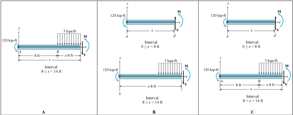
Draw the shear diagram for 0 x 14 ft of the compound beam. Shear and moment diagram for beam with hinge mechanics of materials structurefree. Diagrams for a beam. Express your answers in terms of x separated by comma.
Draw the shear and moment diagrams for the beam. Draw the shear and moment diagrams for the beam. And determine the shear and moment in the beam as functions of x where 4 ft x 10 ft.
Draw the shear and moment diagrams for the shaft. Draw the shear and moment diagrams for the compound beam shown in the figure. Part d shear and moment expressions for segment 2.
Assume the supports at a is fix c is roller and b is pin connections. Draw the shear and moment diagrams for the beam. 200 lb ft b x 4 ft 4 ft 150 lbft 6 ft 200 lb ft a.
14 ft of the compound beam. 12 m 15 m12 m 8 kn 30 knm. This video demonstrates drawing the internal shear and bending moment diagrams for a beam with a hinge.
The attempt at a solution i summed the forces in the y. 3 ft 3 ft 200 lbft 400 lb 6 ft 400 lb a b. Draw the shear and moment diagrams for the compound beam shown in the figure.
Write expressions for the internal shear v and moment m over this segment. 14 ft of the compound beam. The problem statement all variables and givenknown data draw the shear diagram for the compound supported beam.
700 lb 8 ft 4 ft 6 ft 9400 lbft 150 lbft v lb xft xft m lbft 1017 0 317 583 8 141 18 8 9400 1267 162 800 334 9 15. Home study engineering mechanical engineering mechanical engineering questions and answers draw the shear diagram for 0. So sum of moments at any point or forces in any direction are 0 3.
The shaft is supported by a smooth thrust bearing at a and a smooth journal bearing at b. 14 ft of the compound beam. The beam consists of two segments pin connected at b.
To construct the shear diagram first establish. Assume positive moments act counterclockwise. Draw the shear diagram for 0.
Forces in beams beams various. Draw a free body diagram of the segment 8x14 ft on paper. K ft x l l l shear and moment diagrams the slope of the moment diagram over the interval 0 x l.
The shaft is supported by a smooth thrust bearing at.
329 6 1 Draw The Shear And Moment Diagrams For The Shaft The
Solution
Solution
Solution
Mechanics Of Materials Chapter 4 Shear And Moment In Beams
329 6 1 Draw The Shear And Moment Diagrams For The Shaft The
 Determine The Normal Force Shear Force And Moment At Point C
Solution
Mechanics Of Materials Chapter 4 Shear And Moment In Beams
 Solved Shear And Bending Moment Diagrams Learning Goal T
Hibbeler Chapter 6 Part 1 463 486 Qxd
329 6 1 Draw The Shear And Moment Diagrams For The Shaft The
Solution
Solution
250 7500 0 2 V X N
![]() Ch06 07 Pure Bending Amp Transverse Shear
Ch06 07 Pure Bending Amp Transverse Shear
329 6 1 Draw The Shear And Moment Diagrams For The Shaft The
Ch 7 Statics 14th Edition Studocu
 The Hinge Can Transmit A Shear Force But Not A Bending Moment The
Solution
329 6 1 Draw The Shear And Moment Diagrams For The Shaft The
Mechanics Of Materials Chapter 4 Shear And Moment In Beams
0 Response to "Draw The Shear Diagram For 0 X 14 Ft Of The Compound Beam"
Post a Comment