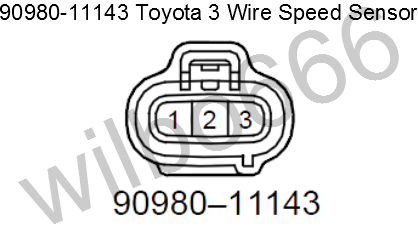
3 Wire Speed Sensor Diagram
Two power wires and one load wire. The transmission pinion shaft rotates and generates four pulses per one rotation.
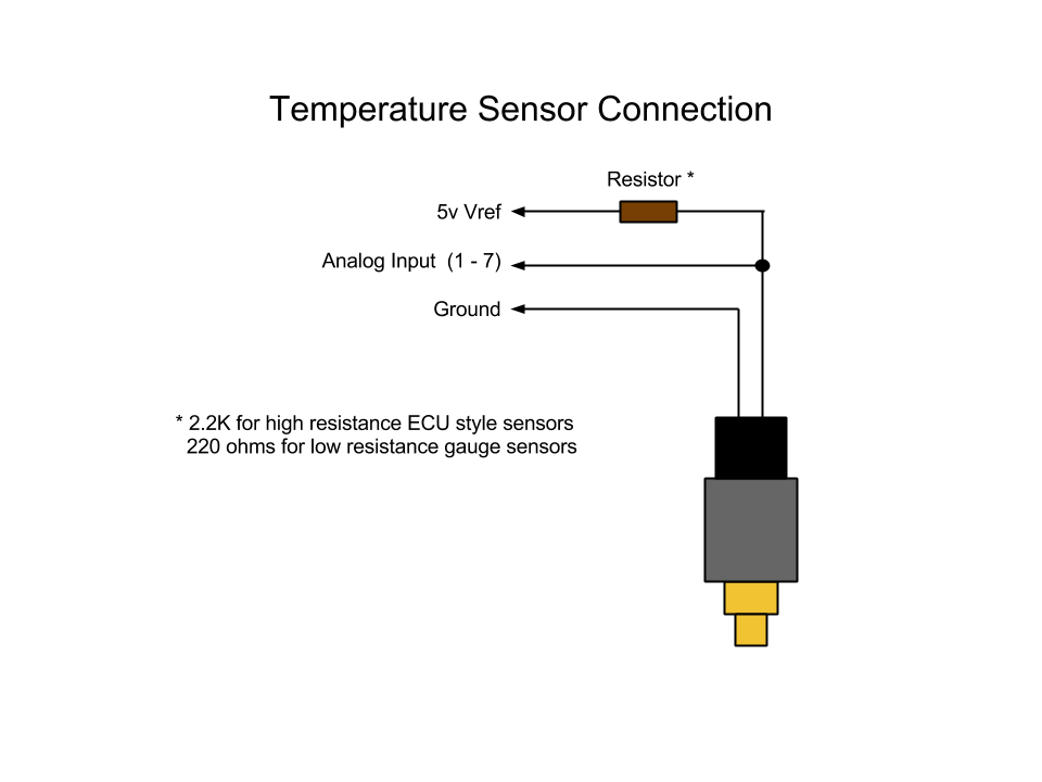 Racecapturepro Sensors Autosport Labs
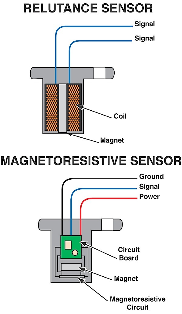
The 3 wire speed sensor is externally powered so you will need a power source of some form.

3 wire speed sensor diagram. Cut the existing connector off where the shrink tube ends. Ebook 3 speed sensor wire diagram currently available at thegreenthimblecouk for review only if you need complete ebook 3 speed sensor wire diagram please fill out registration form to access in our databases. These sensors are self powered meaning the revolutions inside the case generate the signal needed to create movement in the speedometer.
The rate at which the pulses are. Ok some are 2 some are 3. Trying to get a wiring diagram for transmission speedo not working.
The three wire sensor part no. Testing for a speedometer signal download pdf. Standard 78 18 thread 5292 ford plug in gps interface module universal speed sensor 3299 optional tachspeedo gauge connector calibration electric speedometer calibration made easy to calibrate your electric speedometer.
P0501 1998 honda civic speed sensor diagnosis ericthecarguy duration. Its a 3 wire sensor. P0501 speed sensor troubleshooting and wire diagrams to whoever can benefit from this article.
Sn16 works by switching pulsing a reference voltage on and off as the sensor spins. In the past i posted an article on how to troubleshoot this cel code but had problems with the pictures. Driveshaft speed sensor wiring.
The power wires will connect to a power supply and the remaining wire to some type of load. Although the sensor technology may differ all 3 wire sensors are wired the samea three wire sensor has 3 wires present. The vehicle speed sensor is mounted to the transmission.
Peel the shielding away from the three 3 wires in the red cable. There must be a speed sensor usually a two wire. This video has been updated check out the new version here.
Cut them back to where the red wire jacket ends. First off is testing the 2 wire speed sensor. Strip the wire jacketing off both wires.
Electric speedometer recommended auto meter hall effect sender 3 wire 16 pulsesrevolution. Aluminum clear wire. Answered by a verified technician.
Mix how to test a 3 wire speed sender youtube. This is a testing procedure for a 3 wire hall effect style. How to use a multimeter duration.
Aluminum shielding and the clear wire off.
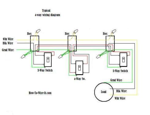 Wire A 3 Way Switch Dead End Additionally 3 Way Switch
 Where Is The Output Speed Sensor Located On A 2008 Ford Edge Limited
 What Is The Difference Between Pnp And Npn When Describing 3 Wire
 How To Wire Discrete Dc Sensors To Plc Part 2 Plc Programming
 Telemecanique Sensor Wiring Diagram Wiring Diagram

 Brushless Ac Axial Fan Engineering From Mechatronics
 Fan Control Schematics Best Part Of Wiring Diagram

Rev Speed Meter Vehiclespecificwiringdiagram
 4 Wire Diagram Wiring Diagram Database
 How To Wire Discrete Dc Sensors To Plc Part 2 Plc Programming
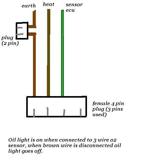
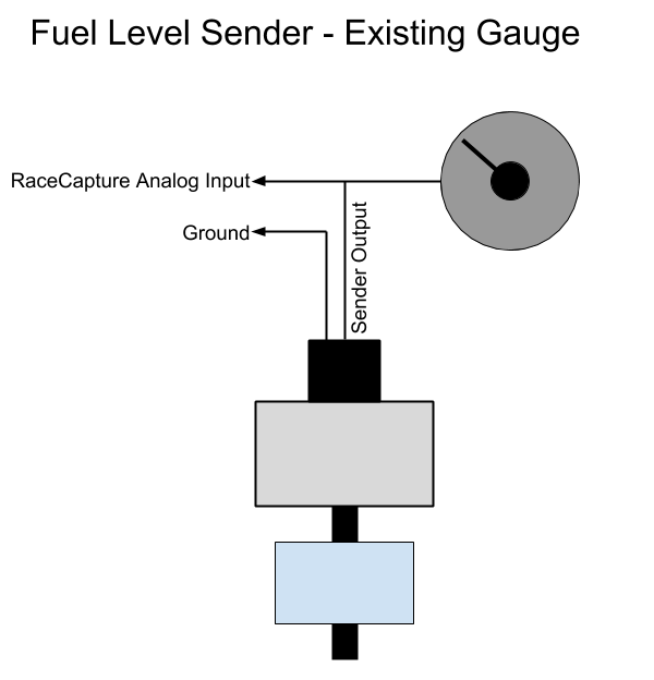 Racecapturepro Sensors Autosport Labs
Ecu Wiring Diagram Required Page 2 Altezza Club Of Nz Australia
0 Response to "3 Wire Speed Sensor Diagram"
Post a Comment