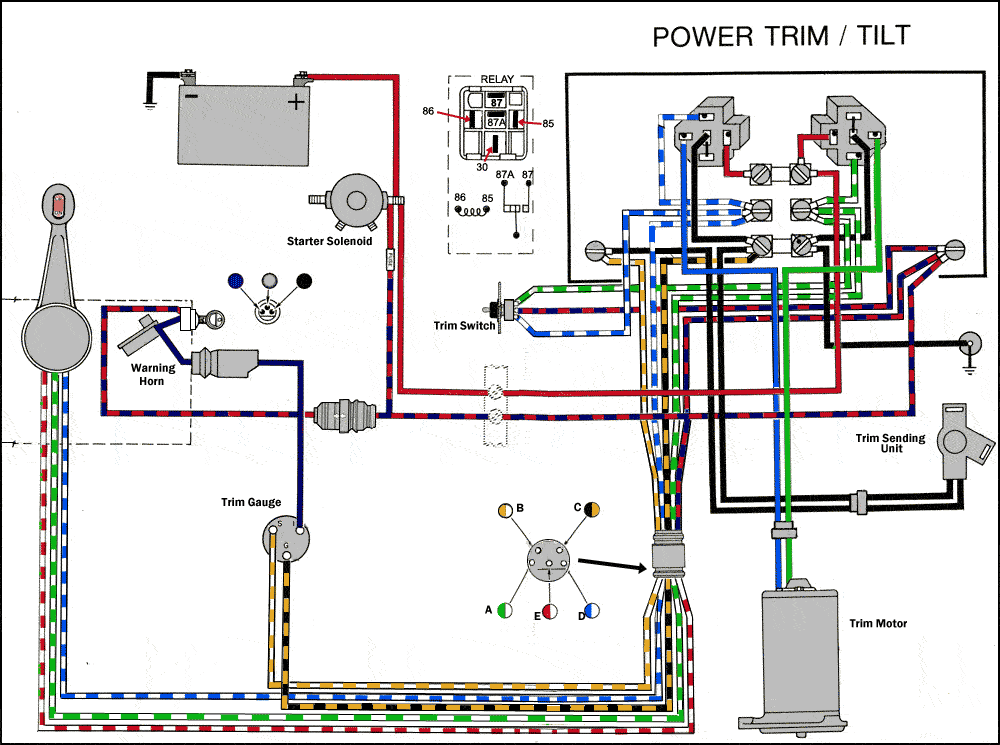
Boat Trim Gauge Wiring Diagram
The thickest wires are 00 or 0 gauge. Power the gauge by connecting a 12 vdc positive wire to the i terminal and a ground wire to the g terminal.
 Mercury Smartcraft Gauges Wiring Diagram Schematic Diagram
See your owners manual for the location and.

Boat trim gauge wiring diagram. View wiring diagrams and schematics for hundreds of popular boats including lowe larson alumacraft lund and others. One should be green and. Ive actually found it practically unnecessary to trim up in most conditions that i boat in except for when pulling the boat in and out of the water.
Wire diagram connectorized case wire diagram 2 116 dia. Finally if your boat is equipped with an ammeter. These get connected in parallel with one dc positive wire and one dc negative wire supplying power to the gauge and enabling a voltage measurement.
The thick red wire. Teleflex gauges technical information. The pointer will slowly move towards the up end of the scale.
Have no other wires connected to the gauge. The smallest gauge allowed on boats for a single wire is 16. Notch deutsch connector case p11 p1a.
Is0016h trim gauge installation instruction. The problem as i see it is either i have the wiring wrong the tt gauge is broken the tach setting is wrong and effecting the tt or the wiring from the tt at the engine to the control. I know before i got the boat the trim motor was replaced and i am sure the power trim and tilt on the control handle should only work with the ignition on.
Find the two heavy gauge wires that lead to the trimtilt pump motor. Of the wire to the boats electrical ground generally. The gauge number the thinner the wire.
Those who dont will provide alternative wiring color codes on a wiring diagram associated with the engine versus the whole boat. 14 steps to wiring your boat. I know for me its helpful to be able to look at the gauge and know what position my trim is in.
I need a simple wiring diagram for a small outboard boat to wire up the lights and few other things but no one seems to have one. The trim gauge can be tested by. Have a wire or terminal that provides the trim gauge signal.
Troubleshooting bypassing wiring spdt tilt trim relay. Engine trim indicator wiring with pics by texaspilot71 august 25 2014 in boat talk. Is there one and where can i find it.
Wiring Diagram Moreover Boat Starter Wiring Diagram On Wellcraft
Mercury Trim Gauge Wiring Diagram Rate Johnson Pump Bilge Pump
 Boat Trim Gauge Wiring Diagram Great Installation Of Wiring Diagram
 Power Trim Wiring Diagram Wiring Diagram Specialties
12 Gauge Wire Conversion Creative Boat Trim Gauge Wiring Diagram
Install Volvo Penta 5 7 Wiring Diagram Toyskids Co
 Boat Voltage Gauge Wiring Diagram Fuel Faria Marine Gauges Vintage
Mercruiser Tilt Trim Diagram Best Wiring Library
 Omc Boat Gauge Wiring Diagram Great Installation Of Wiring Diagram
Marine Gauge Wiring Diagram Troubleshooting Boat Gauges And Meters
 Power Trim Wiring Diagram Wiring Diagram Specialties
 Bass Boat Owners Manuals Skeeter Boats
 Teleflex Trim Gauge Wiring Diagram Schematic Diagram
 Original Misty Harbor Pontoon Boat Parts And Accessories Online
Install Johnson Trim Gauge Wiring Www Toyskids Co
Alpha One Trim Gauge Wiring Diagram Mercury Diagrams Co Tropicalspa Co
Marine Gauge Wiring Diagram Battery Post Wiring Diagrams Wiring
Boat Gauge Wiring Diagram Www Toyskids Co
 Bass Boat Owners Manuals Skeeter Boats
 Wiring Diagram For Gauge Wiring Diagram Database
 Boat Gas Gauge Wiring Diagram Great Installation Of Wiring Diagram
0 Response to "Boat Trim Gauge Wiring Diagram"
Post a Comment