Delay On Break Timer Wiring Diagram
Uses a live or hot inititate switch. 10mc25 is a delay on make delay on break time delay.
 Different Types Of Relays Used In Protection System And Their Workings
Kh1 series fixed time on delay external connection diagram.

Delay on break timer wiring diagram. The time delay on break how it works how to wire into low voltageand why you should have it on your compressor. Mode of operation upon initial thermostat closure the. Delay on break timer wiring diagram download f delay timer wiring diagram.
Delay delay on break timers anti short cycle on delay on break helps to protect air conditioning refrigeration and heat pump equipment from damage which may be caused by the rapid short cycling of compressors. Mode of operation upon application power the load is energized. Variety of delay on break timer wiring diagram.
Delay on break 3 or 5 minutesfixed10 adjustable aps works with anticipator type thermostats installation 1. It is perfect to use when either a magnetic lock or electric strike is installed on an automatic door. Time delay is factory preset to one specific time 5 seconds for example.
Upon closure of a normally open no external initiate switch the load transfers immediately and remains transferred as long as the external initiate switch is closed. Connect terminals as shown in the wiring diagram below. 1 minute 5 minute 10 minute and 15 minute timer circuit diagram.
A wiring diagram is a simplified traditional pictorial depiction of an electric circuit. Tgml timers tgml series cube relay delay on break timers are a unique combination of digital cmos timing circuitry with a relay output in a compact 2 x 2 configuration. The delay on break timer will release the lock and then the delay on make timer will enable the door to open and be held open for a set period of time.
Power is continuously applied to the input terminals of the timer. It reveals the parts of the circuit as streamlined shapes and the power as well as signal links between the devices. View is from the flat side with the catalog numbers.
Off delay delay on release delay on de energization delay on break. Luxury f delay timer wiring diagram image simple wiring diagram. Time delay relay wiring diagram tdrsox srxp time delay relays.
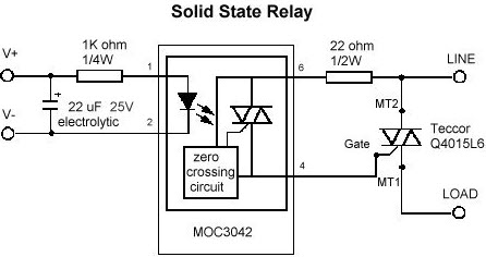
These units provide the same functional perfor mance as plug in relay timers but at significant cost savings. The time delay on break how it works how to wire into low voltageand why you. Module load at pin 2 is a relay coil.
Icm controls icm203 icm203 delay on break timer 03 10 minute knob adjust. Application wiring for fixed dc time delay module figure 3. Reapply power check operation.
Select the desired time delay adjustable models only.
 Switch Schematic Symbols Wiring Diagram Specialties
 Delay On Break Timer Wiring Diagram Inspirational Water Timer


 Delay On Break Timer Wiring Diagram Awesome 12v Time Delay Relay
 Delay On Break Timer Wiring Diagram Lovely Irrigation Pump Start

 Delay On Break Relay Wiring New Era Of Wiring Diagram
 12vdc Delay On Break Timer
 8 New Delay On Break Timer Wiring Diagram Pics Simple Wiring Diagram
 Delay On Break Timer Wiring Diagram Unique Plc Off Delay Timer
 Dayton Timer Relay Wiring Diagram Best Wiring Library
 Icm Time Delay Relay Wiring Diagram Schematic Diagram
4 Wire Trailer Wiring Diagram New Delay Break Timer Wiring Diagram
 Wiring Diagram For Timer Wiring Schematic Diagram
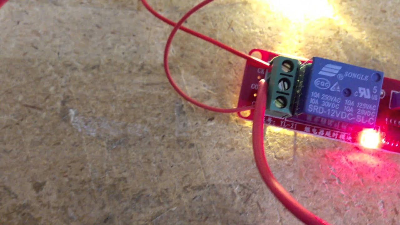 12v Delay Timer Relay 0 10 Seconds
0 Response to "Delay On Break Timer Wiring Diagram"
Post a Comment