Block Diagram To Transfer Function
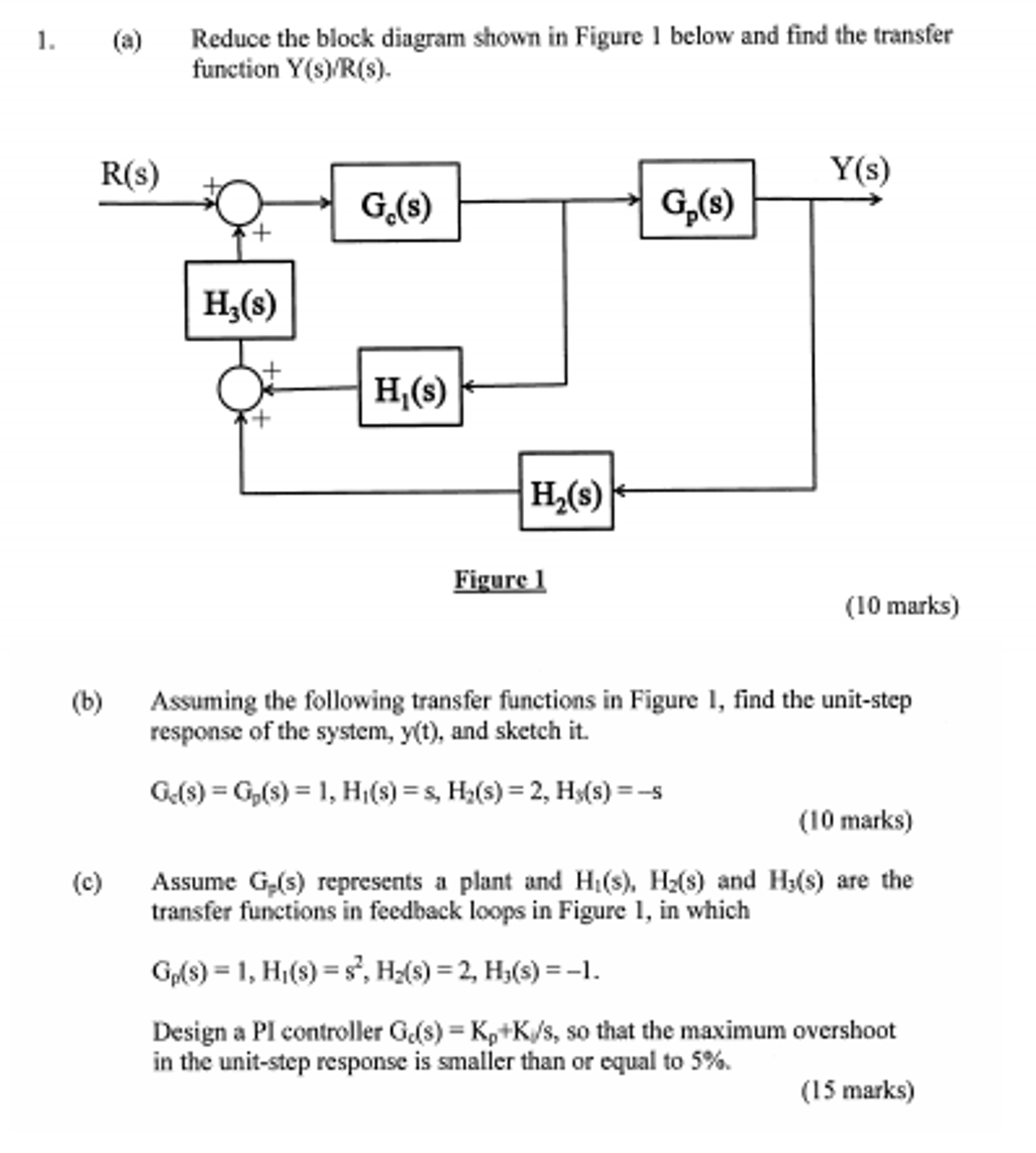
Us g1s xs g2s ys ys g1sg2sus 6. Example problem on how to derive closed loop transfer function from block diagram.
 Block Diagram From Transfer Function Wiring Library
The first step in creating a transfer function is to convert each term of a differential equation with a laplace transform as shown in the table of laplace transforms.
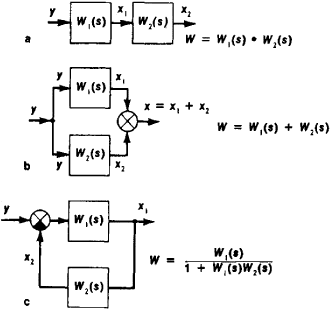
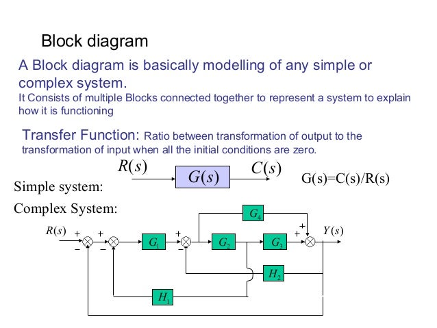
Block diagram to transfer function. Block diagram gives a pictorial representation of a control. When two or more systems are in series they can be combined into a single representative system with a transfer function that is the product of the individual systems. Step 2 repeat step 1 for remaining inputs.
Step 1 find the transfer function of block diagram by considering one input at a time and make the remaining inputs as zero. Methods of obtaining a transfer function block diagram method. The modified form of a block diagram is a signal flow graph.
A block diagram for a feedback control system. Suppose that we have an input signal that is periodic. Step 3 get the overall transfer function by adding all those transfer functions.
The transfer function defines the relation between the output and the input of a dynamic system written in complex form s variable. If we have two systems ft and gt we can put them in series with one another so that the output of system ft is the input to system gt. It is not always convenient to derive the entire transfer function of a complex control system in a single function.
Signal flow graphs. In other words practical representation of a control system is its block diagram. Block diagrams feedback and transient response specifications.
A transfer function g s relates an input u s to an output y s. For a dynamic system with an input ut and an output yt the transfer function hs is the ratio between the complex representation s variable of the output ys and input us. Block diagrams a block diagram of a system is a pictorial representation of the functions performed by each component and of the flow of signals.
It is not convenient to derive a complete transfer function for a complex control system. The block diagram is to represent a control system in diagram form. Transfer functions in block diagrams.
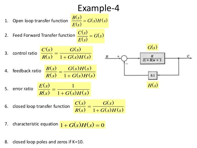
Ys is the output of the block and gs is the transfer function of the blockecm2105. This module introduces the concepts of system block diagrams feedback control and transient response specifications which are essential concepts for control design and analysis. This command loads the functions required for computing laplace and inverse laplace transforms.
Ak sinkωtbk coskωt where ωis the fundamental frequency of the periodic input. The basic idea of the transfer function comes from looking at the fre quency response of a system. It is easier and better to derive transfer function of control element connected to the system separately.
Block Diagram Automatic Control Article About Block Diagram
![]() Block Diagram Of Cnc Machine Tool Control System A Transfer Function
Block Diagram Of Cnc Machine Tool Control System A Transfer Function
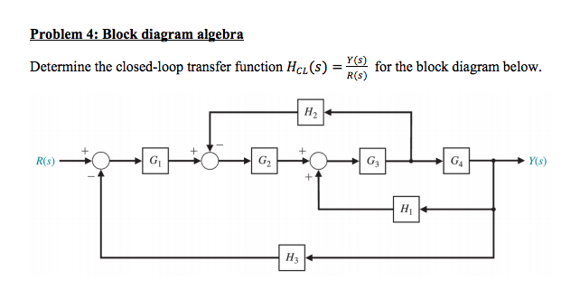 Solved Problem 4 Block Diagram Algebra Determine The Clo
 Block Diagram Representation Of Control Systems
![]() Chapter 3 Dynamic Response The Block Diagram Block Diagram Is A
Chapter 3 Dynamic Response The Block Diagram Block Diagram Is A
![]() Block Diagram Transfer Function Reduction Block Wiring Diagram
Block Diagram Transfer Function Reduction Block Wiring Diagram
![]() Transfer Functions Block Diagram Download Scientific Diagram
Transfer Functions Block Diagram Download Scientific Diagram
![]() Ppt The Block Diagram Powerpoint Presentation Id 5668999
Ppt The Block Diagram Powerpoint Presentation Id 5668999

![]() Block Diagram Of Dc Motor S Transfer Function Mathematical Model
Block Diagram Of Dc Motor S Transfer Function Mathematical Model
 Solved Find The Transfer Function For The Block Diagram S

 Closed Loop Transfer Function Wikipedia
Conversion Between State Space And Transfer Function Representations
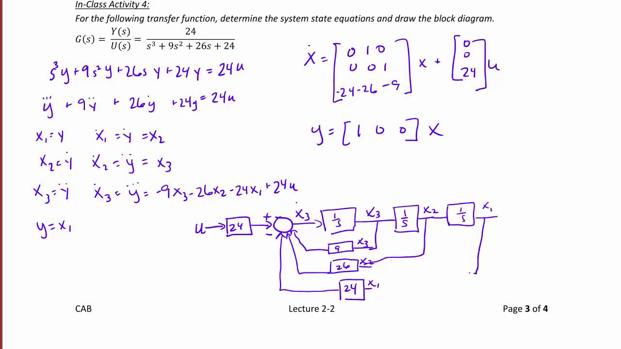 Ece320 Lecture2 2b State Equation Solutions Transfer Functions
 Closed Loop System And Closed Loop Control Systems
![]() Block Diagrams And Their Transfer Functions For The Exact
Block Diagrams And Their Transfer Functions For The Exact
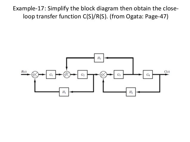
 Block Diagram Reduction Techniques
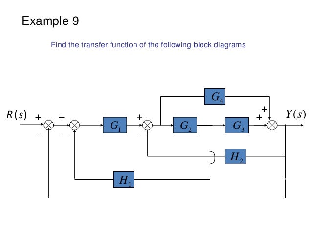 Block Diagram Examples
 Block Diagram Examples
0 Response to "Block Diagram To Transfer Function"
Post a Comment