Yamaha Trim Gauge Wiring Diagram
Then your trim sender will send the signal through the command link circuit. How to wire up a yamaha outboard gauge by will charpentier.
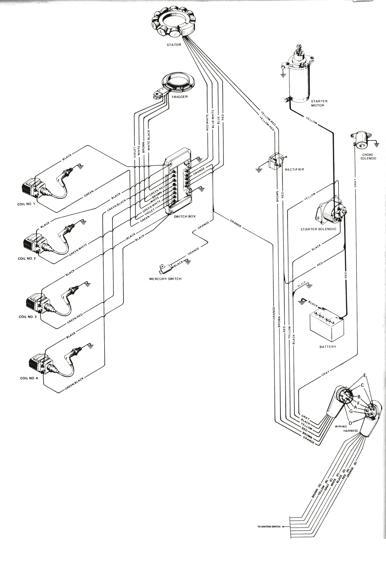 Mercury Outboard Wiring Diagrams Mastertech Marin
Set and mode buttons below.

Yamaha trim gauge wiring diagram. Other one with speed trip time and gas pump icon across top. Theres an accommodation for an analog sensor a boss in the top of the no. I have the schematic at work when i get there later today if you need more assistance.
Fuel gauge bar graph is vertically to the right. Ill look into the color code at the console. 1 cylinder which permits the installation of a temperature gauge.
The use of a schematic diagram solves this problem. Discussion in boat electronics started by gil marlin may 23. Pointer will read full up all but the johnson evinrude and suzuki 4 stroke 2002 outboards they will read full down.
You just need a color coded wiring diagram. It is a single wire. The trim gauge can be tested by.
Yamaha outboards are cooled by raw water with a bypass valve that opens when the cylinder head reaches a preset temperature. In electrical wiring the term lavender is not used as a wire insulation color. Wire insulation is usually violet.
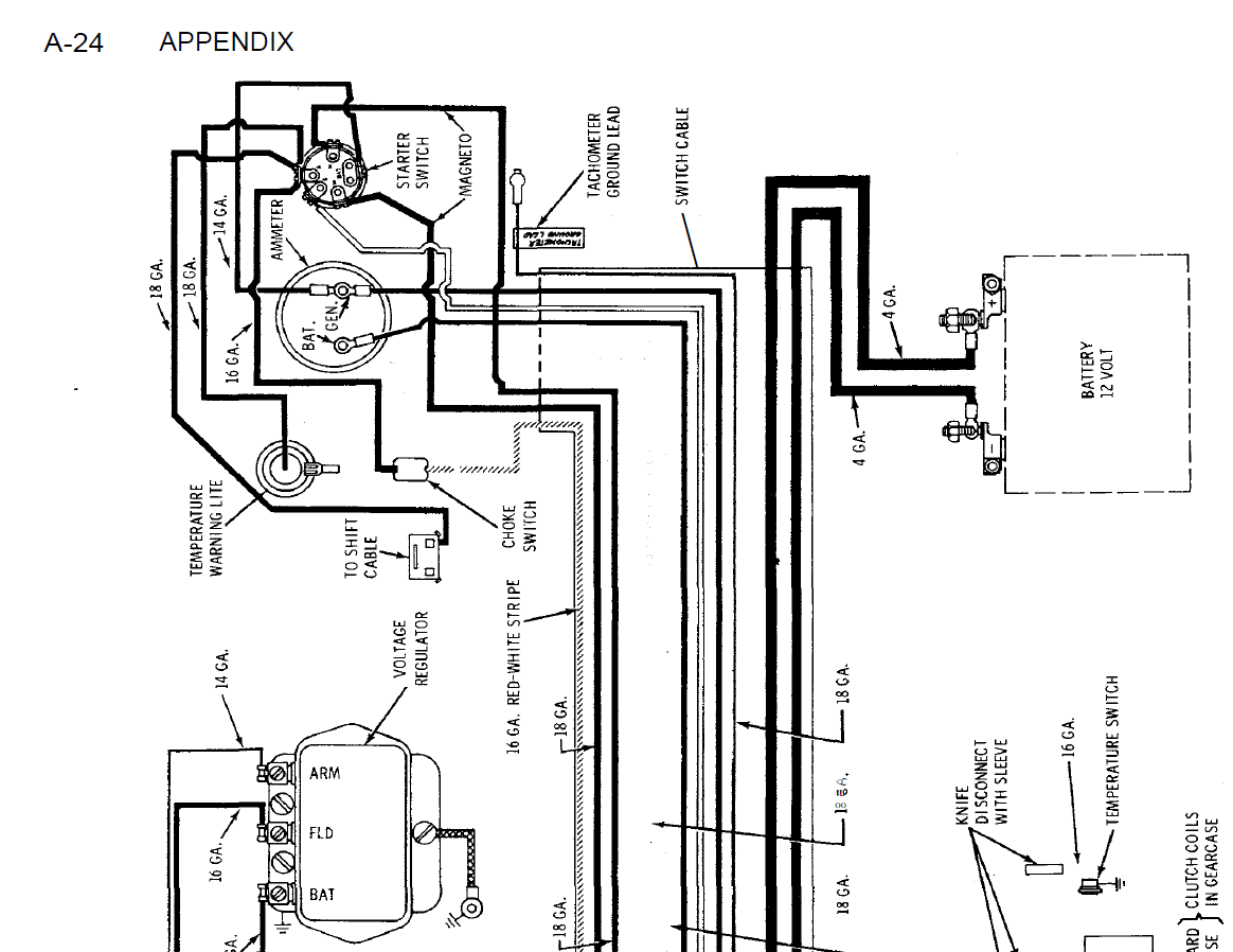
Troubleshooting bypassing wiring spdt tilt trim relay. Typically in the owners manual for a yamaha motor you will find an electrical schematic diagram that shows the connection of devices like the trim gauge. Apr 15 2007 1.
The thick red wire. Have no other wires connected to the gauge. Have 3 older lcd marine meters.
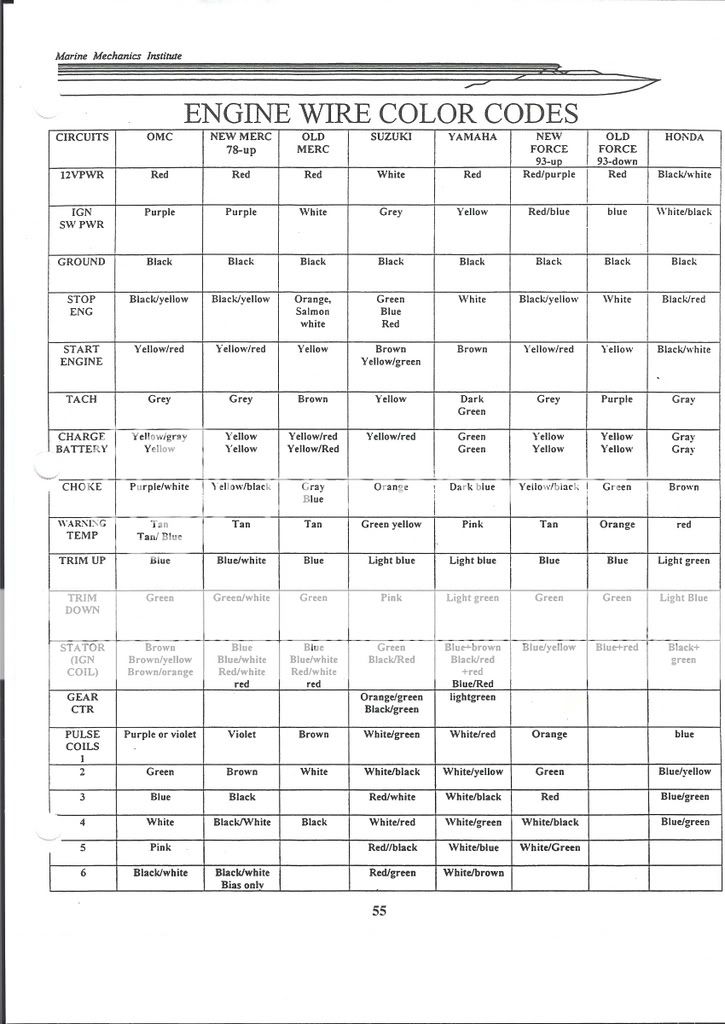
And temp battery and gas pump icon below. There is an industry standard set of wire codes in general use by most manufacturers except yamaha. One should be green and.
Find the two heavy gauge wires that lead to the trimtilt pump motor. Power the gauge by connecting a positive wire to the i terminal and a ground wire to the g terminal. Installing trim guage on yamaha discussion in bubbas outboards started by grumper apr 15 2007.
I am looking for wiring diagrams for ignition and gauges for 1989 yamaha 200s etxf and letxfs. See your owners manual for the location and color of this wire. The trim gauge wires do connect up to the harness at the engine.
2 tachs working fine. Wiring color codes here is a listing of common color codes for yamaha outboard motors. Wiring diagram for yamaha command link tachometer kit.
Bobpaul apr 18 2007. Be certain to use stranded insulated wire not lighter than 18 awg that is approved for marine use. All outboard motors and ios that have a trim control have a wire or terminal that provides the trim gauge signal.
 Troubleshooting Teleflex Engine Trim Gauges
 Yamaha Motorcycle Parts Jpcycles Com
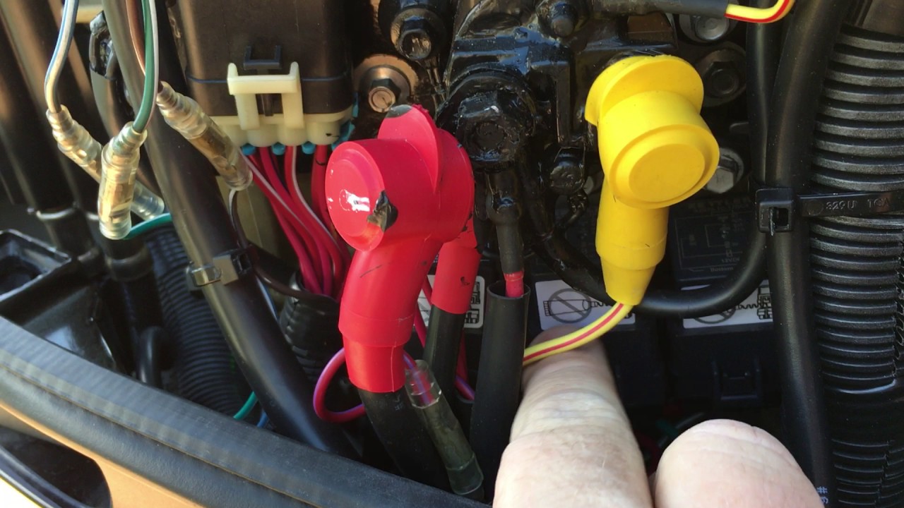
 Yamaha Vmax 150 Tilt Trim Repair Youtube

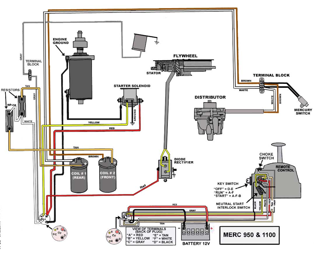
 F70 Yamaha Trim Gauge Wiring Schematic Diagram
 Trim Motor Relay Replacement Mercury Optimax 250hp 2005 Outboard
Yamaha Multifunction Gauge Kit Installation
 Engine Wiring Diagram Yamaha 40 Hp Outboard Wiring Diagram
 Outboard Also Mercury 800 Outboard Wiring Diagram Also Yamaha
 Cmc Tilt And Trim Wiring Diagram Wiring Schematic Diagram
Yamaha Multifunction Gauge Kit Installation
 Yamaha Outboard Control Wiring Schematic Diagram

 Western Star Trucks 4900


Yamaha Multifunction Gauge Kit Installation
 Boat Trim Gauge Wiring Diagram Great Installation Of Wiring Diagram
 The Atlas Jack Plate And Atlas Jack Plate Accessories T H Marine
 Maintaining Your Trim Tab System Bennett Marine
0 Response to "Yamaha Trim Gauge Wiring Diagram"
Post a Comment