Iron Iron Carbide Phase Diagram
1100 1000 for example lets consider the eutectic point of iron with a 077 c content while it is being. The left side of the diagram is pure.
 Iron Iron Carbide Equilibrium Phase Diagram 15 Download
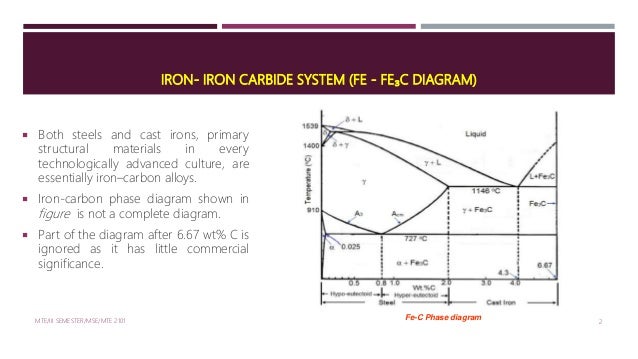
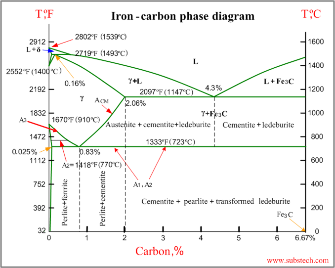
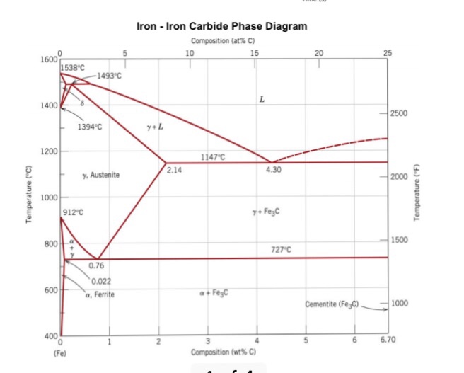
Iron iron carbide phase diagram pure iron has two crystalline forms one bcc commonly called α iron which remains stable from low temperatures upto 910c 1414f when it changes to fcc called γ iron.

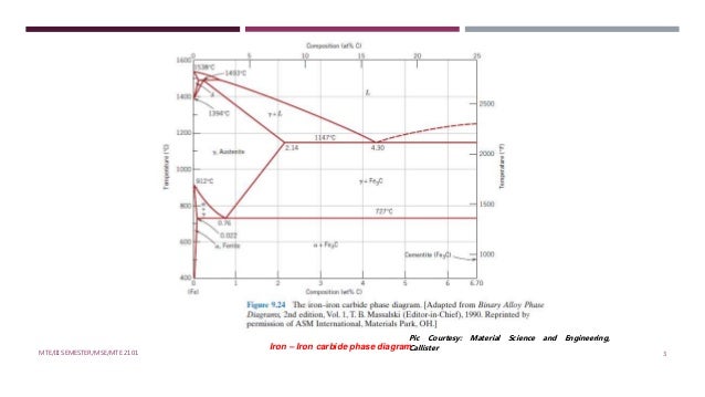
Iron iron carbide phase diagram. Therefore iron iron carbide diagram even though technically represents metastable conditions can be considered as representing equilibrium changes under conditions of relatively slow heating and cooling. Figure 1 shows the equilibrium diagram for combinations of carbon in a solid solution of iron. Examples of heat treatment.
Component and system a component is defined as pure metals of which an alloy is composed. The iron carbide is called metastable phase. O phase transformations between phases with different densities annealing temperatures are relatively low so that useful effects of cold working are not eliminated.
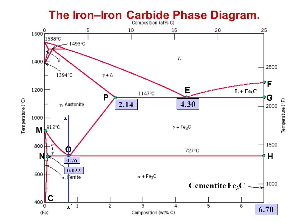
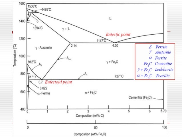
This graph is known as iron iron carbide equilibrium diagram. The diagram shows iron and carbons combined to form fe fe 3 c at the 667c end of the diagram. Five phases are α ferrite bcc fe c solid solution γ austenite fcc fe c solid solution δ ferrite bcc fe c solid solution fe 3 c iron carbide or cementite an inter metallic compound and liquid fe c solution.
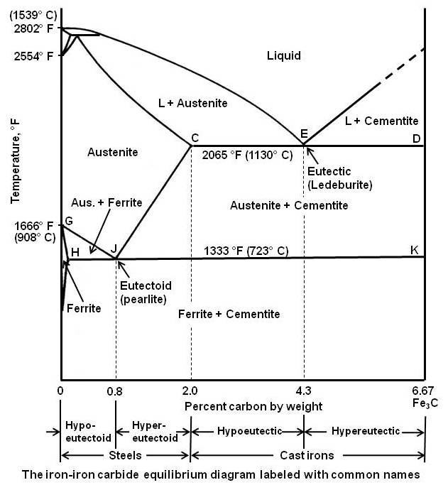
The fe c phase diagram is a fairly complex one but we will only consider the steel part of the diagram up to around 7 carbon. Phase equilibria for a 996 wt fe 040 wt c at a temperature just below the eutectoid determine the following a composition of fe 3c and ferrite α b the amount of carbide cementite in grams that forms per 100 g of steel c the amount of pearlite and proeutectoid ferrite α. This is the between pure iron and interstitial compound iron carbide fe c containing 667 carbon by weight.
The iron iron carbide fe. The iron iron carbide fe fe 3 c is defined by five individual phases and four invariant reactions. Contents levers rule eutectic reactions eutectoid reactions peritectic reactions cu ni phase diagram pb sn phase diagram al si phase diagram iron iron carbide diagram 4.
The ironiron carbide fefe3c phase diagram in their simplest form steels are alloys of iron fe and carbon c. C phase diagram. The portion of iron carbon alloy system that is of interest is shown in fig.
Fe fe 3 c phase diagram clickable materials science and metallurgy 4th ed pollack prentice hall 1988. The iron iron carbide phase diagram and the development of microstructures in steels various microstructures can be developed depending on the carbon content the amount of plastic deformation working and the method of heat treatment.
 The Iron Carbon Phase Diagram
 Mme 291 Lec 05 Pptx Iron Iron Carbide Phase Diagram Common
 Ppt The Iron Iron Carbide Phase Diagram Powerpoint Presentation
Phases And Microstructure
 The Iron Carbon Phase Diagram
 60 Inspirational Iron Carbide Phase Diagram Images Wsmce Org
 Iron Iron Carbide Phase Diagram
 Module 5 Metallic Materials Ppt Video Online Download
 Iron Iron Carbide Phase Diagram
 Iron Carbon Phase Diagram
 Gate Metallurgical Engineering Iron Iron Carbide Phase Diagram

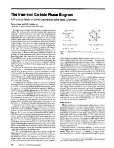 The Iron Iron Carbide Phase Diagram A Practical Guide To Some Pdf

Iron Carbon Phase Diagram A Review See Callister Chapter 9

0 Response to "Iron Iron Carbide Phase Diagram"
Post a Comment