How To Wire An Ignition Switch Diagram
Follow the path of the battery wire from the switch to the next connection point. How to wire stuff up under the dash.
 Basic Gm Ignition Wiring Best Part Of Wiring Diagram
Different fuse panels have different attachment methods.
How to wire an ignition switch diagram. Note that only one wire power wire can run a few circuits on the fuse panel. Identify the terminal labeled battery among the connections shown on the ignition switch diagram. You use jumper wires.
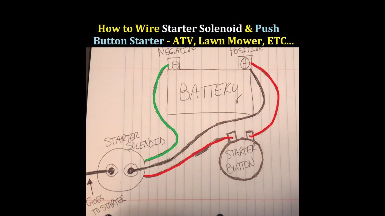
However once the tractor is running. Connect the power lead from the battery to the batt terminal of the switch. To begin with the negative battery terminal must be disconnected before locating the positive power lead to the switch.
This is followed by installing the right terminal end on the power lead wire and connecting it to the battery terminal. When the tractor is cranked the starter requires the full capacity of the batterys voltage. Disconnect the negative battery terminal.
It should be in the upper portion of the schematic. Fuse panel ignition switches etc. How to wire the ignition switch on a tractor.
How to wire an ignition switch. In addition the ignition switch mechanically controls the amount of voltage sent to the coil of the starter by switching between two circuits. Some aftermarket ones come with them and others you just make your own.
The procedure for wiring an ignition switch is as follows. Wiring diagrams are also available for the entire wiring system of fords and chevys and other foreign and american made cars. Now to wire up your fuse panel look at the following diagram.
If your motorcycle has a starter the next point should be the solenoid. Determine which one is appropriate for your ignition switch. Some ignition switches use a cross tip screw to secure the wires and some use spade clips on the wire ends.
Install the wire on the ignition switch and tighten the retaining screws with a wrench. Route the wires to the fuse box location and install the wires on the box. The run wire should be 10 gauge the accessories wire 12 gauge and the start wire 14 gauge.
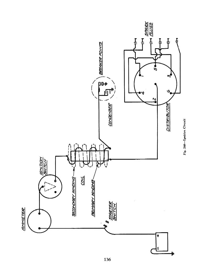
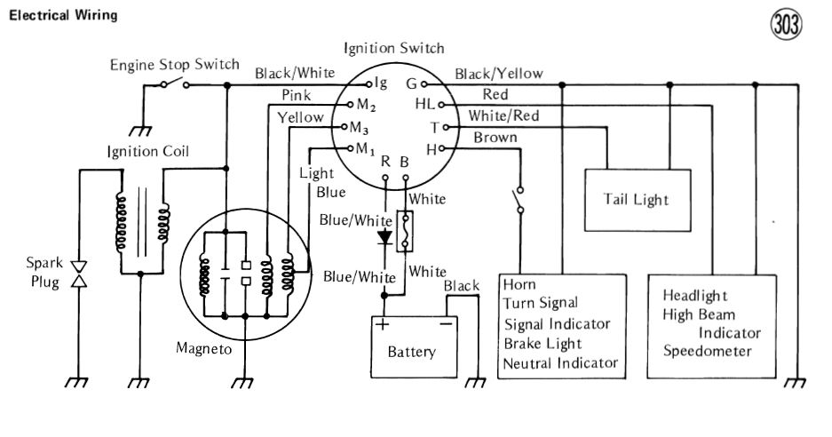
An ignition switch wiring diagram provides the schematics that are needed to enable auto owners to fix any wiring repairs related to their ignition system.

 Wiring Diagram Tractor Ignition Switch Wiring Diagram Ignition
 Wiring Diagram Tractor Ignition Switch Wiring Diagram Ignition


Technical Ez Wiring The H A M B
 Kawasaki Key Switch Wiring Diagram 1 Wiring Diagram Source
 Nissan 240sx Ignition Switch Wiring Diagram Wiring Diagram
 Wiring A Ignition Switch Great Installation Of Wiring Diagram
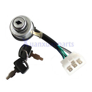 Chinese Gasoline Portable Generator 6 Wire Ignition Key Combination
 Mustang American Autowire Wiring Harness 1965 1966 Installation

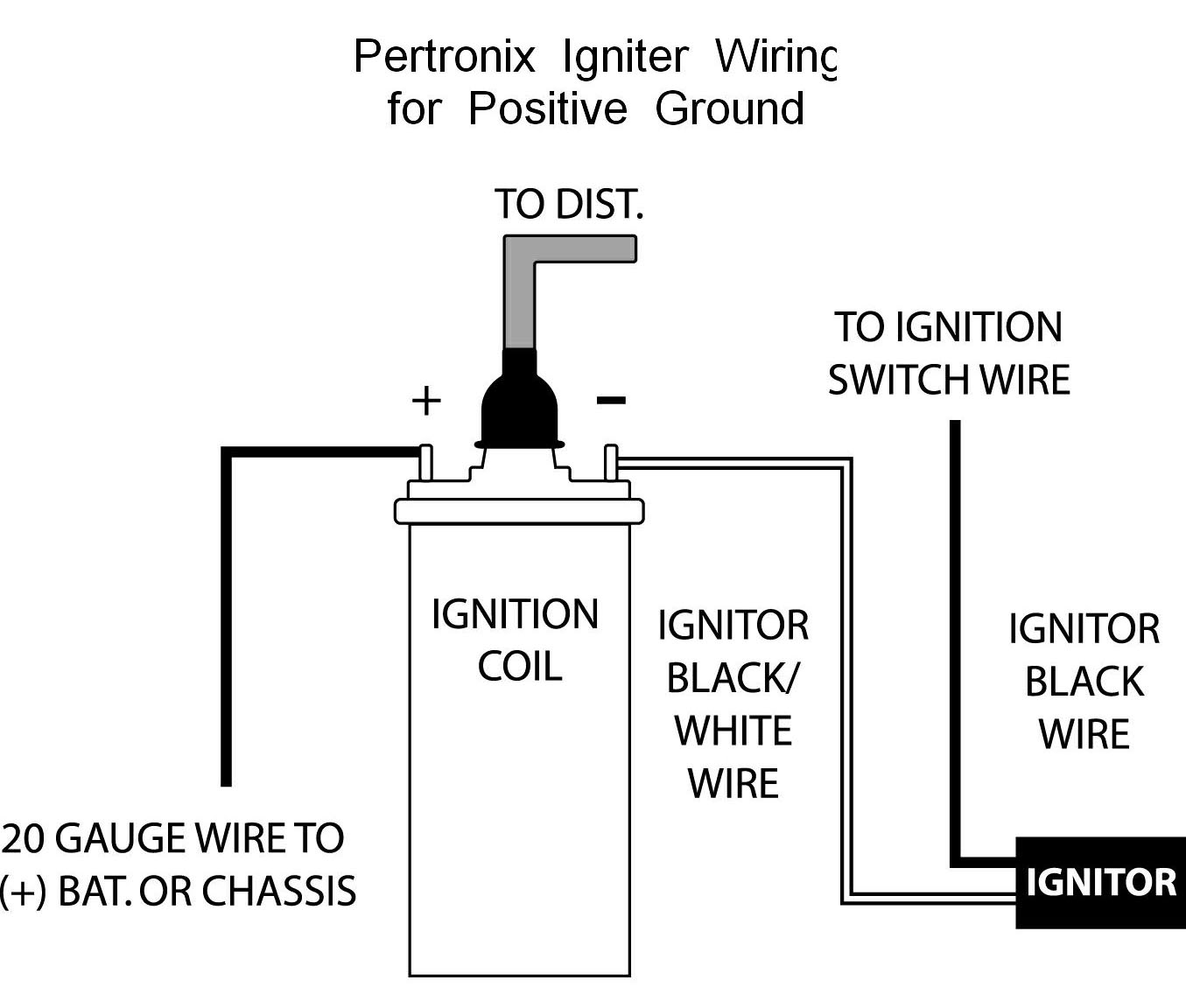
 Wiring Diagram Ignition Coil Plug Black Or Wiring Diagram
 Arctic Cat Atv Ignition Wiring Diagram Wiring Diagram


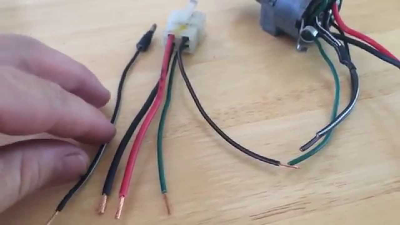 Ignition Switch Wires Help Honda Elite 250 Youtube
 Wiring Diagram Ignition Coil Plug Black Or Wiring Diagram
0 Response to "How To Wire An Ignition Switch Diagram"
Post a Comment