Start Stop Push Button Wiring Diagram
I need help wiring the following diagram. C i m nc.
Wire Diagrams For Cars Schematic Diagram
I have 2 push button stations.
Start stop push button wiring diagram. I need the motor to turn on and off by using either pushbutton station. Pilot light l2 4 2 3 pilot light start stop bulletin 1495 normally closed auxiliary contacts are required. T w 6.
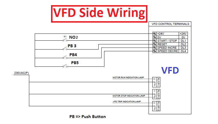
Start stop push button station wiring diagram fresh basic blueprint exactly whats wiring diagram. Vfd start stop wiring diagram. Use the top diagram to help you figure out how to wire it.
Start stop push button station wiring diagram. Start stop 3 phase motor starter wiring. Thanks for any help.
Show more i need help wiring the following diagram. Start stop 3 wire control. Please show me how to wire 3 2 and l1 to the pushbuttons.
View profile view forum posts. Starting a three phase motor. How does vfd start stop wiring diagram work.
Mpcbmccb uses to control input supply of your vfd control the circuit by onoff the push button. The start button is normally open and the stop button is normally closed. There may be times when it is desirable to have more than one start stop push button station to control a motor.
Contactor or relay to use the startstop push button. Wiring a push button stop start switch. Then wire one of the contacts in on the contactor to turn on light 1 whenever the contactor energizes.
Starting a three phase motor. Start stop 3 wire control. Typical wiring diagrams for push button control stations 7 start stop control wiring diagrams single station with motor stopped pilot light l1 start l2 i 1 stop 2 oi 3 n wol.
Rl1 and rl2 contacts should be taken from the vfd feedback relays. Motor starter schematic and wiring diagram. Here mcb uses to control the input supply into the circuit.
Ladder diagram basics 3 2 wire 3 wire motor control circuit. I have attached a simple latching circuit diagram your existing contactor should be ok for this. How to wire push buttons with a holding circuit with for a contactor coil.
I have 2 push button stations. In this chapter the basic start stop push button control circuit will be modified to include a second stop and start push button. Kontrol kontaktor dengan push.
Steve 04 02 2011 0627 pm 3. A wiring diagram is a type of schematic which makes use of abstract pictorial symbols to show all the interconnections of components in a system.
110 Volt Schematic Diagram Start Stop Great Installation Of Wiring
Wiring A Start Stop For Motor Control Great Installation Of Wiring
 Mcc Panel Wiring Diagram Pdf Along With Abb Vfd Control Wiring
 Start Stop Wiring Diagram Fresh Start Stop Push Button Station
Start Stop Switch Push Button Wiring Diagram Box Annwertzgarvin Com
Pushbutton Relay Selector Circuit Diagram 1 Wiring Diagram Source
 A Three Wire Start Stop Circuit With Multiple Start Stop Push Buttons
 Diagram Chevy Ignition Switch Wiring Diagram Toyota Starter Relay
 Pushbutton Relay Selector Circuit Diagram 1 Wiring Diagram Source
34897d13098044673waycircuitwontilluminate3wayjpg 1 Wiring Diagram
 Relay Wiring Diagram In Addition Latching Relay Circuit Ladder
Hvac Thermostat Wiring Wiring Library
 One Line Start Stop Wiring Diagram Www Toyskids Co
Pushbutton Relay Selector Circuit Diagram 1 Wiring Diagram Source
 Basic Ladder Diagram 1 Wiring Diagram Source
Relay Wiring Diagram In Addition Latching Relay Circuit Ladder
 Basic Ladder Diagram 1 Wiring Diagram Source
Start Stop Station Wiring Diagram Also Organisedmum De
Pushbutton Relay Selector Circuit Diagram 1 Wiring Diagram Source
 Relay Switch Schematic Schematic Diagram
 Relay Circuit Problems Schematic Diagram
0 Response to "Start Stop Push Button Wiring Diagram"
Post a Comment