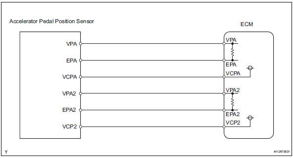
Accelerator Pedal Position Sensor Wiring Diagram
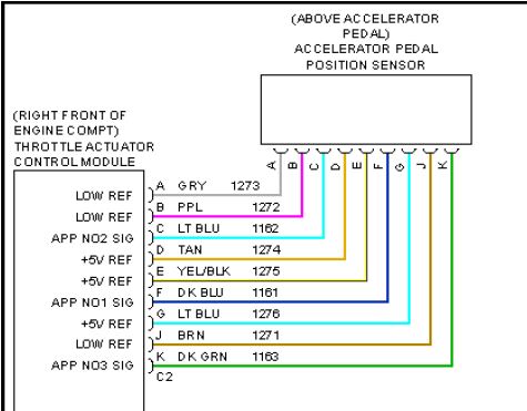
Electronic throttle motor wires identification. Dtc p2122104 throttlepedal position sensorswitch d circuit low input.
 Info Toyota Hilux 1kz Te Repair Toyota Service Blog
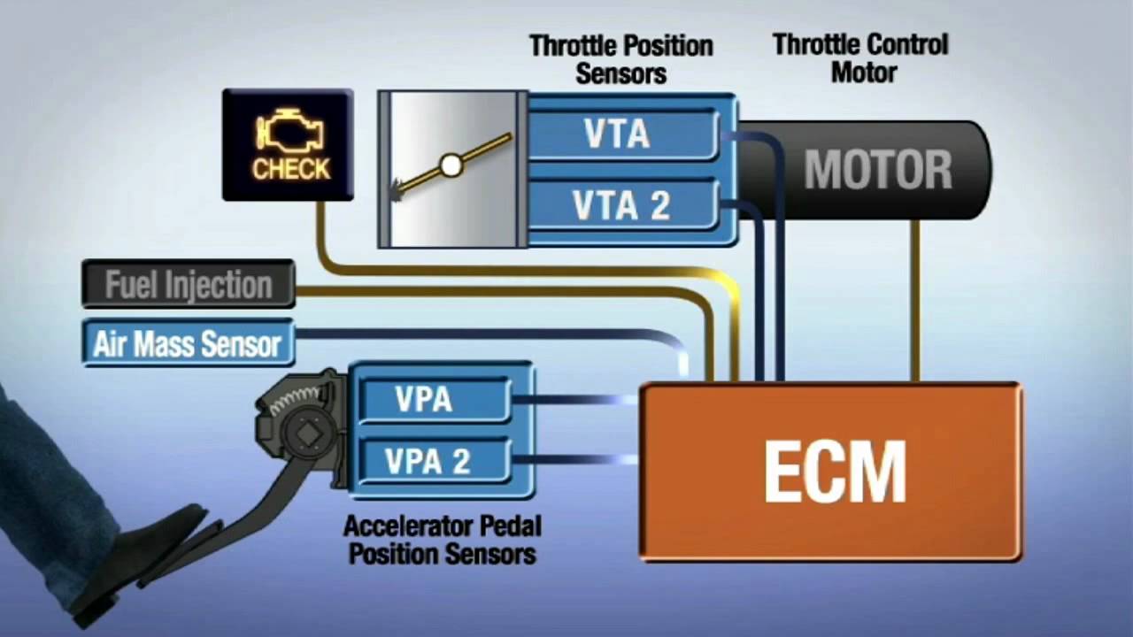
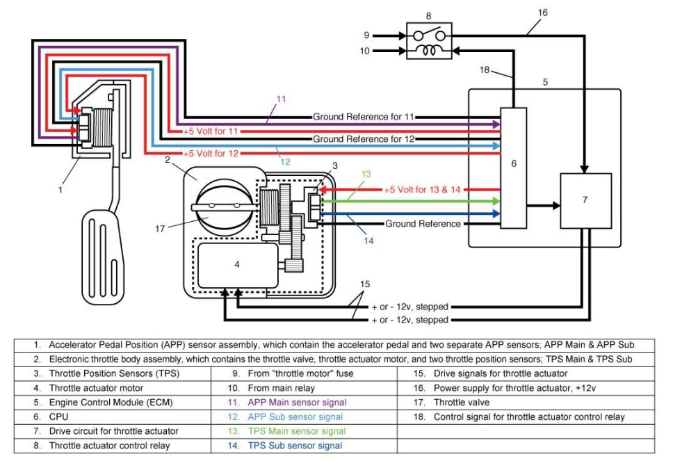
To inform the engine control module of accelerator pedal and throttle plate position.

Accelerator pedal position sensor wiring diagram. 2003 ssangyong rexton main fuse box diagram 2003 ssangyong rexton main fuse box map fuse panel layout diagram parts. It is a potentiometer with one end connected to 5 volts from the vcm and the other to ground. Use and appropriate wiring diagram and always verify.
Throttle position sensor wiring diagram 1997 1998 ford 4 6l 5 4l toyota rav4 service manual throttle pedal position sensor repair guides diesel electronic engine controls accelerator. Immobilizer control unit accelerator pedal position sensor glow plug injector cylinder glow control unit ac control unit engine control unit. Integral to the servomotor in this particular instance is the tps throttle position sensor.
Wiring diagram inspection procedure 1 read value of handheld testeraccel pos 1 and 2 a connect the handheld tester to the dlc3. The voltage output from this particular sensor has to report back to the ecm the exact position of the throttle butterfly. A third wire is connected to the vcm to measure the voltage from the tps.
Yes they only connect to the ecm signal is most likely sent via can bus. Tp sensors are normally mounted on the throttle body with the throttle plate shaft running into the sensor. In depth info on throttle position sensor.
The throttle position sensor tps is connected to the throttle shaft on the throttle body. With this in mind the tps in the same manner as the throttle pedal position sensor has two voltage. You can also find other images like diagram wiring diagram diagram parts diagram diagram replacement parts diagram electrical diagram.
The signal on channel 2 is offset by 075 v to the signal from channel 1 over the complete range of the sensor. Accelerator pedal position sensor connector vcp2 a13 front view vpa ep2 epa. Accelerator pedal position sensor wiring diagram here you are at our site this is images about accelerator pedal position sensor wiring diagram posted by maria nieto in accelerator category on feb 14 2019.
I just made a quick check of the wiring diagrams and it looks like the pedal sends a signal to the ecu then the ecu to the tcu. 00777 accelerator position sensor g79 27 10 implausible signal intermittent. Welcome to the throttle position sensor page.
Lab scope measurement of accelerator pedal position sensor the signals from channel 1 red and channel 2 yellow are the two potentiometers of the acceleration pedal position sensor. This procedure is a mute point if you have the wiring diagram but often times you just need to actuate the electronic throttle to do a cleaning.


 Note Electronic Throttle Control System Etcs May Also Be Referred To


 1998 Dodge Stratus Diagrams Air Bag Sensors Locations 2005 Dodge
 Isx Cm2250 Ecm Diagram Www Picswe Com
 Tps Wiring Harness 10 Ulrich Temme De
 Electronic Throttle Control Lexus

 Dodge Ram Dash Light Wiring Diagram Auto Electrical Wiring Diagram
 Tps Wiring Diagram Schematic Diagram
 Wiring Diagram Jeep Wj Schematic Diagram

0 Response to "Accelerator Pedal Position Sensor Wiring Diagram"
Post a Comment