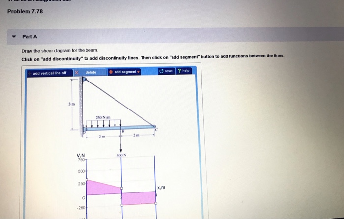
Problem 778 Part A Draw The Shear Diagram For The Beam
Draw the shear diagram for the beam. Solved problem 7 80 part a draw the shear diagram for solved f6 12 draw the shear and moment diagrams for.
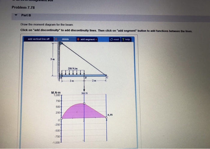 Solved Problem 7 78 Parta Draw The Shear Diagram For The
Click on add vertical line off to add discontinuity lines.

Problem 778 part a draw the shear diagram for the beam. Then click on add segment button to add functions between the lines. Draw the shear and moment diagrams for the shaft. The course covers shear force and bending moment diag.
No part of this manual may be displayed reproduced or distributed in any form or by any means without the prior written permission of the. Of solved draw the shear and moment diagrams for simply solved draw the shear and moment diagrams for linearl solved draw the shear and moment diagrams for beam us. Click on add discontinuity to add discontinuity lines.
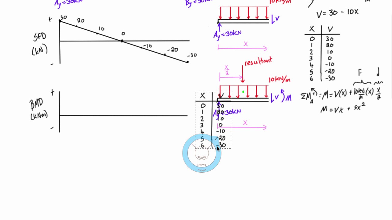
In each problem let x be the distance measured from left end of the beam. Problem 544 draw the shear and bending moment diagrams for the beam and loading shown and determine the maximum absolute value a of the shear b of the bending moment. Draw a free body diagram of the section between the cut and one end of the beam.
Then sum forces in the y direction to get the shear on the cut section. Draw the shear and moment diagrams for the beam. Also if i add up all the areas under my shear lines i get 7309.
Solution reaction at a. This tutorial goes over how to draw the shear force diagram and bending moment diagram of a cantilever beam that is. Also draw shear and moment diagrams specifying values at all change of loading positions and at points of zero shear.
Correct problem 753 part a draw the shear diagram for the beam. Draw the shear and moment diagrams for the beam. Video lecture on problem 1 on sfd and bmd for cantilever beam from chapter shear force and bending moment diagram of subject strength of materials for mechanical civil automobile engineering.
Write shear and moment equations for the beams in the following problems. Then click on add segment button to add functions between the lines. The support at a is a thrust bearing and at b it is a journal bearing.
Home study engineering mechanical engineering mechanical engineering questions and answers 778 draw the shear and moment diagram for the beam. Your shear diagram is correct.
 Shear Force And Bending Moment Diagrams Example 3 Distributed Load
 Chapter 6 Wall Construction 2015 International Residential Code
 Study Of The Star Forming Regions In The Spiral Galaxy Ngc 2336
329 6 1 Draw The Shear And Moment Diagrams For The Shaft The
Ch 7 Statics 14th Edition Studocu
1 Introduction
 Modeling The Bending Vibration Of Cross Laminated Timber Beams
12 0 Appendices
P 1050 2 Nehrp Recommended Seismic Provisions For New Buildings And
 Solved Problem 7 78 Parta Draw The Shear Diagram For The
Aci Structural Journal Technical Paper Shear Strength Of Thin Webbed
Performance And Capacity Of Isolated Steel Reinforced Concrete
Statics And Dynamics Me35a Fall 2008
Statics And Dynamics Me35a Fall 2008
Untitled
 Behavior Of Fully Grouted Reinforced Concrete Masonry Shear Walls
329 6 1 Draw The Shear And Moment Diagrams For The Shaft The
 Pdf Shear Strength Of Thin Webbed Post Tensioned Beams
12 0 Appendices

Investigation Of Adhesive Test Methods For Thick Bondline Joints
 Applied Sciences Free Full Text Seismic Behaviors Of Concrete
0 Response to "Problem 778 Part A Draw The Shear Diagram For The Beam"
Post a Comment