How To Draw Shear Force And Bending Moment Diagram
Since beam is symmetrical. For the ease of understanding we will discuss the same example what we have discussed in the shear force diagram tutorial.

The area under the sfd above the x axis should equal the area between the x axis and the sfd below the x axis.

How to draw shear force and bending moment diagram. Things to keep in mind. Both of the reactions will be equal. The calculations are only set to draw the shear force and bending moment of a beam at the moment.
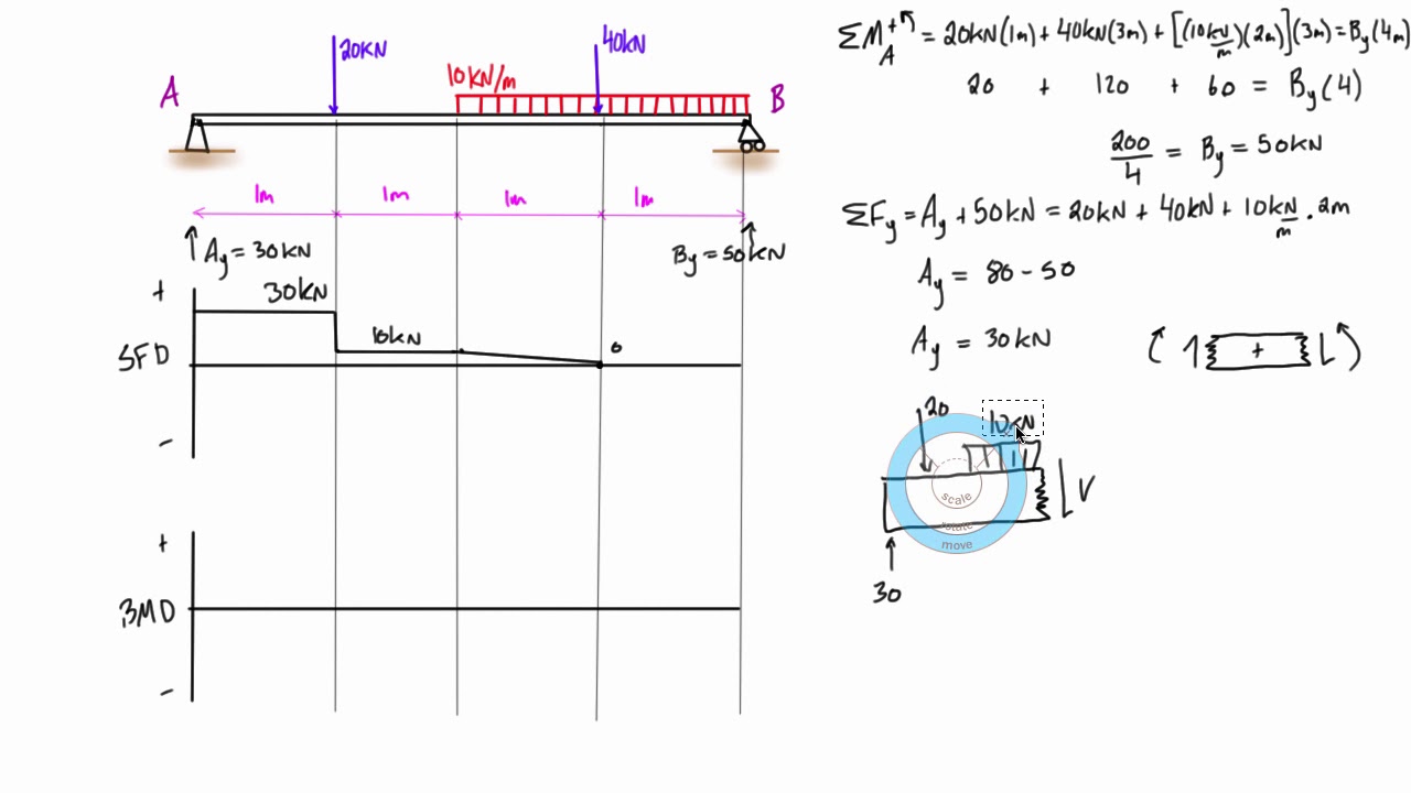
Finally calculating the moments can be done in the following steps. Check this is true in our above example. Once you have the reactions draw your free body diagram and shear force diagram underneath the beam.
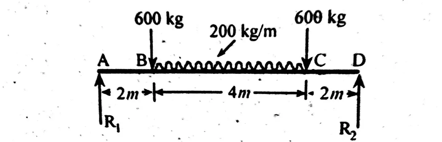
As shown in figure below. Ie the area should sum to zero. Ie r1 r2 w2 1000 kg.
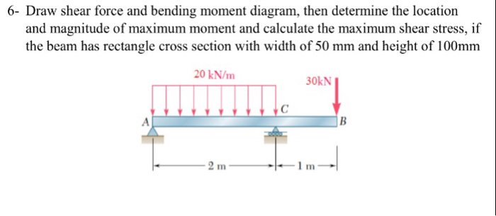
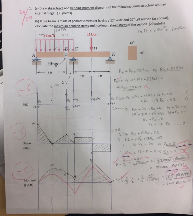
Calculate reactions at supports and draw free body diagram fbd. The bending moment at the two ends of the simply supported beam and at the free end of a cantilever will be zero. It will teach you how to find and draw bending moment diagrams shear force diagrams and the reactions of simple beams.
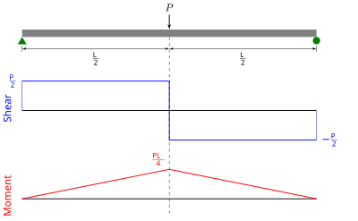
The method indicates the concept used for bending. First find reactions of simply supported beam. Draw shear force and bending moment diagram of simply supported beam carrying point load.
This will help you become better at calculating all typed of these problems and you will certainly be ahead of the curve the next time you need to know how to do this. Shear force between any two vertical loads will be constant. This is a tutorial to make shear force diagram and bending moment diagram easily for a simply supported beam loaded with concentrated loads.
If you need a free frame calculator or free truss calculator there are a range of other free tools available at skyciv. You have finished calculating and drawing shear and bending moment diagrams as well as an approximate deflection diagram. Simply supported beam with point load example.
If youre not sure how to determine the reactions at the supports please see this tutorial first. The shear force diagram of the above example looks like below. And hence the shear force between the two vertical loads will be horizontal.
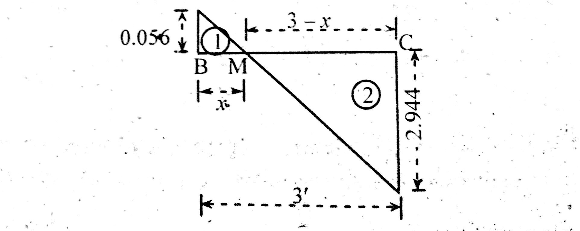
Any points where the sfd cross the x axis will be a max or min bending moment. You will know the important five steps required for how to calculate and draw bending moment diagram. These are very important tools and skills for an engineer to have and are a very integral part of your undergraduate college degree program.
 Shear And Moment Diagram Wikipedia
 Shear Force And Bending Moment Diagram Example 5 Mixed Distributed
 Shear Force And Bending Moment Diagrams This Website Is Useful
 Nptel Mechanical Engineering Strength Of Materials

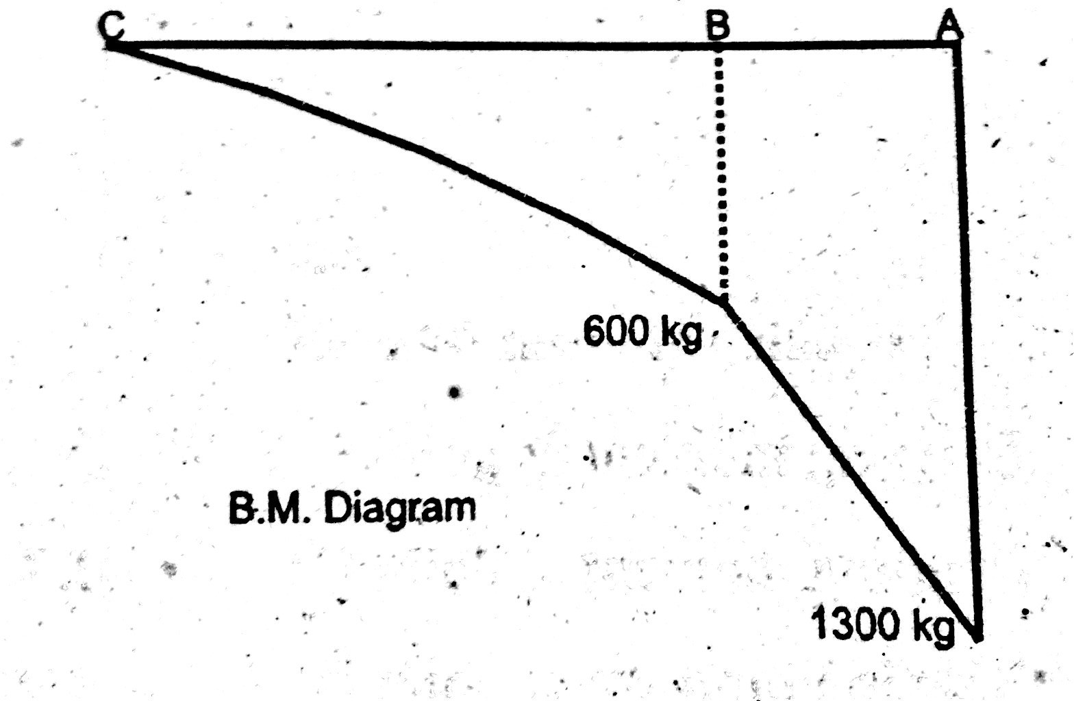
 Shear Force And Bending Moment Diagram For Frames
 This Video Explains How To Draw Shear Force Bending Moment Diagram
 Shear Force Diagram Calculator Kv Diveteam Detmold De
 Nptel Mechanical Engineering Strength Of Materials
 Shear Force And Bending Moment Diagrams Wikiversity
 Nptel Mechanical Engineering Strength Of Materials
 How To Calculate And Draw Shear And Bending Moment Diagrams 13 Steps
 Structure Analysis I Lecture 8 Internal Loading Developed In
 Shear Force And Bending Moment Diagram Practice Problem 1 Youtube
Example 1 Draw The Shear And Bending Moment Diagrams For The
0 Response to "How To Draw Shear Force And Bending Moment Diagram"
Post a Comment