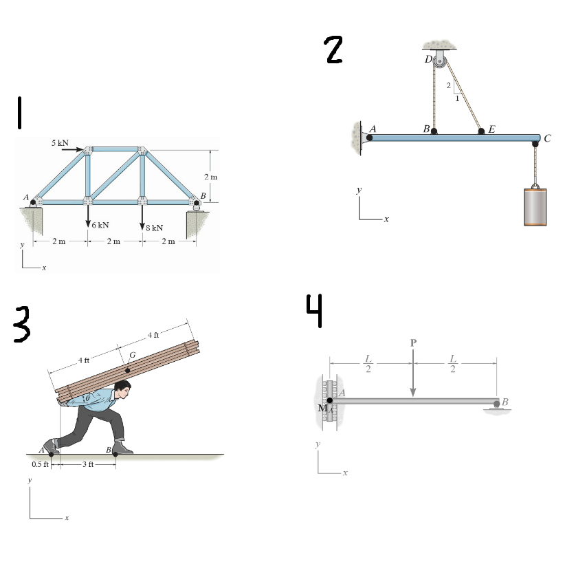
Draw The Free Body Diagram For The Truss A Is A Pin And B Is A Rocker
Radius ofof 6150 in. 19 37 free body diagrams wednesday october 3 2012 new support conditions.
 Determine The Horizontal And Vertical Components Of Reaction Youtube
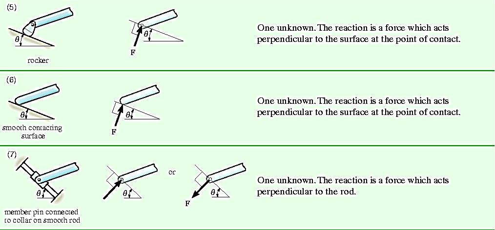
At this support there is a force that either pushes or pulls on the system.
Draw the free body diagram for the truss a is a pin and b is a rocker. Idealized model free body diagram fbd 1. Neglect his weight and friction force between the floor and the man. Draw a free body diagram of bar ac below.
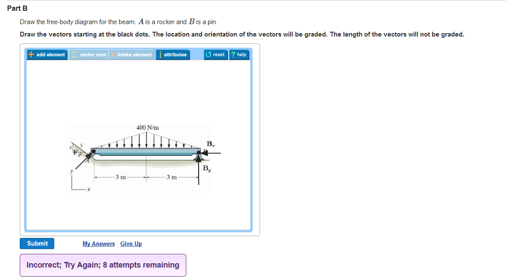
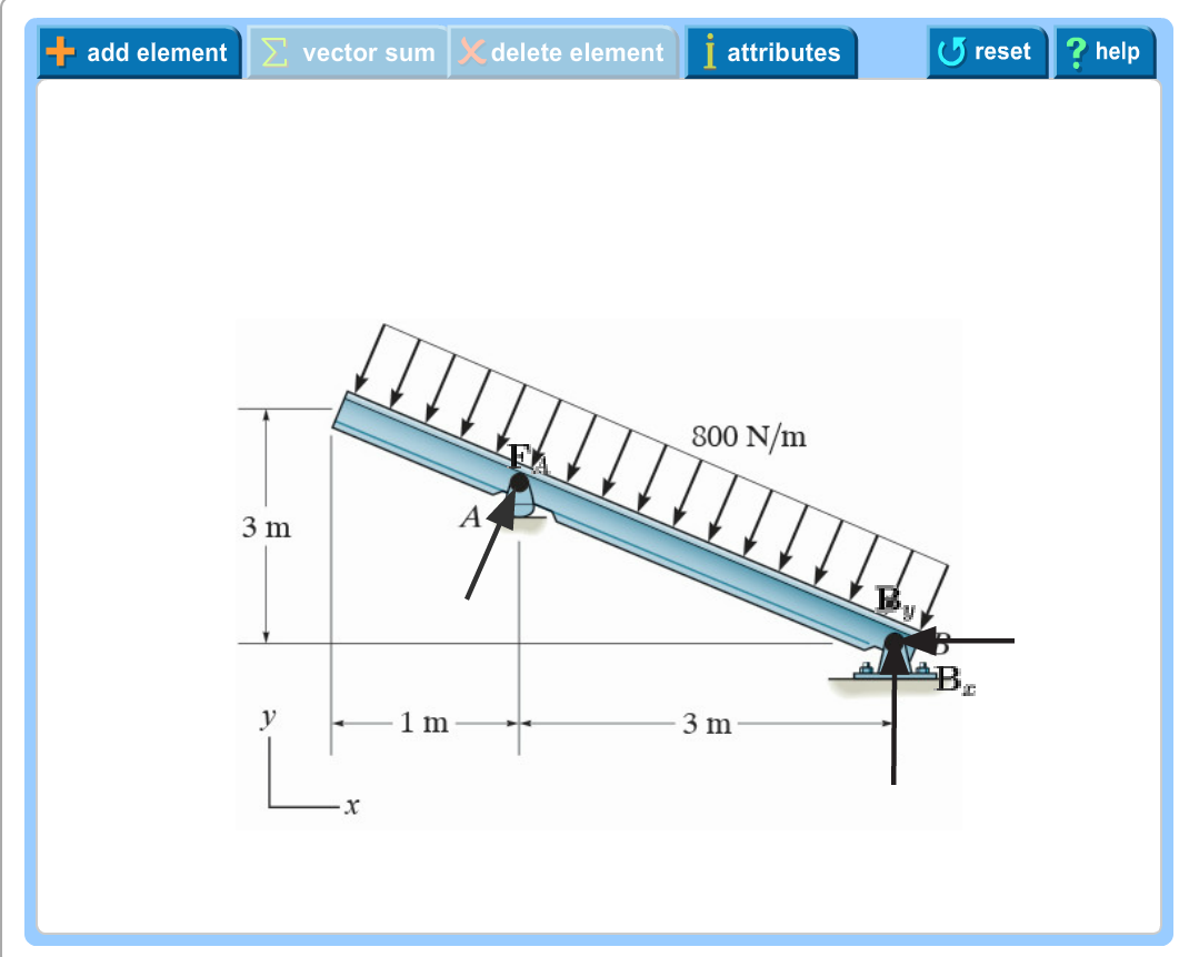
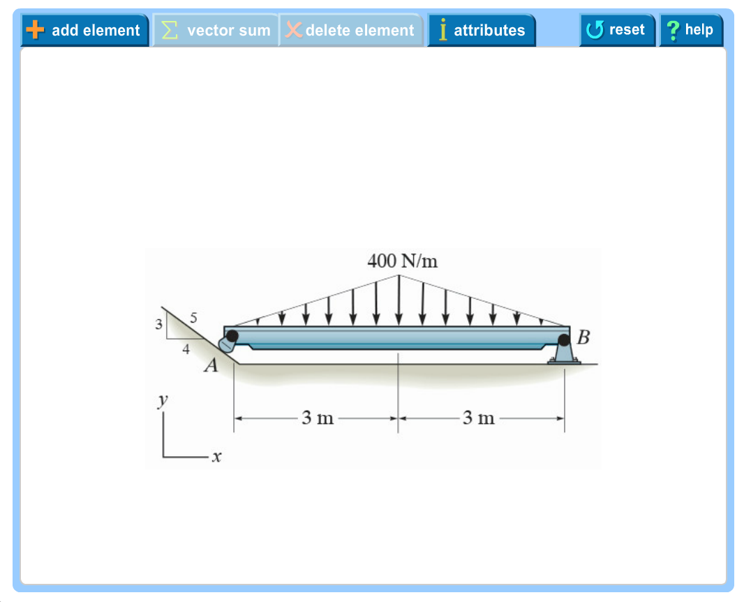
Draw the free body diagram for the beam. Free body diagrams are consequently often called equilibrium diagrams. Draw the free body diagram of the winch which b 3 in.
The man stands on a smooth floor. Now replace the bracket at a in the preceding frame with another bar. A is pin and b is a rocker.
Rigid body equilibrium free body diagrams and the equations of equilibrium. Draw the free body diagram for the beam. Draw the free body diagram for the truss.
Part a draw the vectors starting at the black dots. Determine the force resisted by each bolt at the wall and the normal force at b for equilibrium. The length of the vectors will not be graded.
At point h link. Draw a fbd of pulley b. Draw a fbd of bar ac.
Draw the free body diagram for the man and load. Support is provided by a bolt or pin located at each end a and a and by the symmetrical brace arms which bear against the smooth wall on both sides at b and b. Show all the external forces and couple moments.
Free body diagram method of joints and method of sections intuition. Ititisispin connected pin connectedatat its center c and at its outer rim is a ratchet gear having a mean a 502mm in. A is a pin.
The location and orientation of the vectors will be graded. Truss analysis by method of joints. Draw a fbd of the hook assembly c.
The line of action of the force is along the axis of the link. A is a pin and b is a rocker. Draw the free body diagram for the beam.
Draw a fbd of the 1000 lb weight. The above diagrams which show the complete system of applied and reactive forces acting on a body are called free body diagrams. The whole system of applied and reactive forces acting on a body must be in a state of equilibrium.
There are a number of ways to draw pin connections here is a pin connecting two members. Draw the free body diagram for the truss. Imagine the body to be isolated or cut free from its constraints and draw its outlined shape.
Free body diagrams section 52 2. Draw an outlined shape. This really shows you what method of joints and method of sections actually are.
According to sir isaac for every action there is an equal and opposite reaction. Roller or rocker. 222 ch 6 drawing a free body diagram.
A applied loads b support reactions and c the weight of the body. Consists of of aadrum drumofofradius radius 4 mm.
 Homework Iii Chapter 5
 Chapter 5 Equilibrium Of A Rigid Body Alvick Lau Academia Edu
 Solved Part B Draw The Free Body Diagram For The Beam Ai
 Solutionmanual 5a Fatih Demir Academia Edu
 Hinged Ridge Joint A With Dowelled Steel Plate End Plate And
Engineering Mechanics Statics 12th Ch05 Solutions Studocu
 Draw Body Diagram Xt5 Lektionenderliebe De
 Ishik University Sulaimani Architecture Department Structure
 Solved Draw The Free Body Diagram For The Beam A Is A Ro
Me 101 Engineering Mechanics
 Simple Trusses Engineering Mechanics Questions And Answers
Rigid Body Equilibrium
Chap 2 Force Vectors
Announcements Trusses Method Of Joints
Solution
 Solved Part 1 Draw The Free Body Diagram For The Truss
 Solved Draw The Free Body Diagram For The Beam A Is A Ro
Problem 5 1 In Active Example 5 1 Suppose That The Beam Is
Powerpoint Presentation 13 Trusses
Engineering Mechanics Statics In Si Units 12e


0 Response to "Draw The Free Body Diagram For The Truss A Is A Pin And B Is A Rocker"
Post a Comment